Andy132
Members-
Posts
29 -
Joined
-
Last visited
Contact Methods
-
Website URL
https://leatherworker.net
Profile Information
-
Gender
Male
-
Location
Victoria, Australia
-
Interests
Canvas work.
LW Info
-
Leatherwork Specialty
Canvas.
-
Interested in learning about
Machine maintenance,helping others with same,sewing techniques.
-
How did you find leatherworker.net?
The web.
Recent Profile Visitors
The recent visitors block is disabled and is not being shown to other users.
Andy132's Achievements

Member (2/4)
-
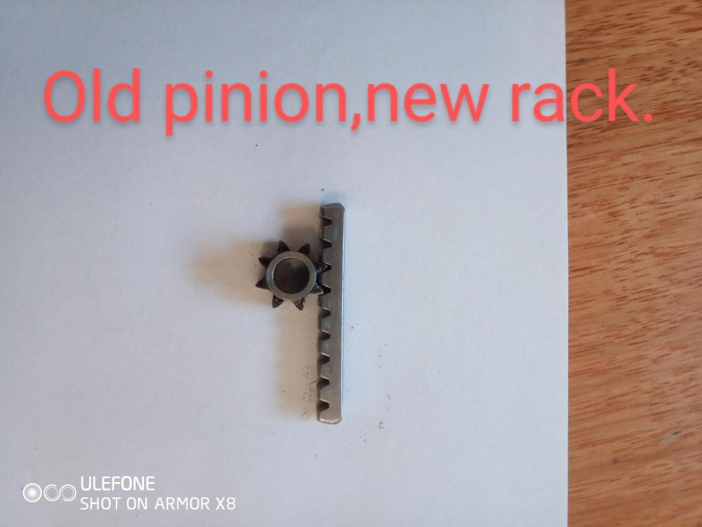
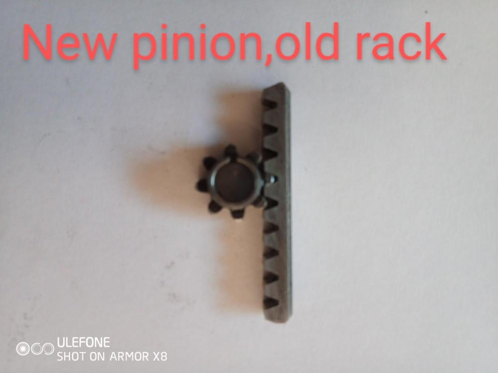
I then used the two new racks and the old following pinion. The play in the drive pinion isn't too bad but the slight slack in the freewheel teeth transfer slop back to the shuttle plate movement still. It seems fairly excessive - about 2mm,but until the whole lot is put together and tried out, I'm not going to know if it affects the stitches. I recall in an older post,Wizcrafts referencing no more than 1/16 " of play in the shuttle,I think I'm still over that. After a bit of measurement and digging around on the net,it seems that all of the new racks and pinions are utilizing the Mod 1 standards for gears. Which makes sense given it's industry standard for a lot of items made throughout Asia. Particularly model RC cars. I was interested to see the amount of different sized pinions available for rc's and the potential for adaptation to our machines. However,the smallest size I can see is 10 teeth,not the 8 that we require. I've ordered some 10 teeth stock for the interests of measuring and adaptation, There is plenty of corresponding Mod 1 rack available - cheaply, but the smallest dimensions I could find it in were 10mm x 10mm ,not the 4.2 x 4.5mm the new racks measure at. My thoughts were,the following pinion could easily be machined to specs, the nominal bore on the rc pinions comes in various sizes,5 mm being the closest. That can easily be reamed out with some wet n dry to the 5.4mm that my pinion post at least,measures at. My thoughts for the drive pinion,were- machine the stepped bush to dimensions,drill and fit a grubscrew to the backside of it. Mark where the shuttle drive sits in its normal resting position. Fit the pinion stock,locate the racks and pinion in position and tighten the grubscrew. I realize by this point, everybody is shaking their heads and thinking," just buy the parts". This is just a thinking exercise for when the part quality or availability is not there,as in my following pinion saga. Be happy to hear others thoughts or if anyone else has looked at alternative gearing etc? The Mod or dp gearing comes in much smaller toothed variants ,so theoretically,a Mod • 5 could be used- racking and pinions from the rc world- that would allow larger toothed pinions in the same space, and tighter precision on the overall mechanism?? Ok, enough - I need to do something constructive with my day. Andy.
-
So, yesterday, I was able to get the drive pinion ( new one) working. The solution settled on was to emery down the step section of the pinion bush until the tapered holes lined up This meant removing approximately - •3/•35mm of material off the bottom. As mentioned earlier,the effects of this was to cause the shuttle driver and pinion to bind on the bush as they no longer had the clearance required in the step of the pinion bush. Luckily for me, someone in the past had retro fitted a 71 mdl shuttle driver bush to the arm. I removed this carefully and spent a couple of house with a flat sheet of glass, different grades of wet n dry emery paper rubbing down the larger diameter surface that the pinion runs on. Removed slightly more material than what I removed off the pinion. Eventually,I was able to screw the tapered screw into the two holes fully - with the necessary clearance to the bush so that both parts move freely,but without slop.
-
Cheers Tastec, that's another way for me to try the photos. I tried an app yesterday and before I knew it,they had all of the photos in my phone on their site, including some banking ones and rego shots. Information they really didn't need to have,but that's the slimy nature of the tech world,so I wiped the app. That's a complete and thorough road you've taken on the clean up, I was pretty happy with the results from electrolysis and Scotch Brite. The first few bits flash rusted pretty quickly after I washed them down which defeated the purpose,so what I started doing after the final bath was taking it straight out and up to the shed. Wiped it down with an old towell and hit it with the air compresso,then the heat gun. Wiped it down with some acetone and out in the sun and no more flash rust. An hour later,gave a coat of etch primer. Your method sounds more what I'd do if I was seeking the best result for a showroom finish though. Very precise and no corners cut, I applaud you. Truth is, I'm a bit rough at times... I have the wire wheel on the bench grinder,agree there is nothing like it for getting the metal work back to its prime. The cloth wheel would be great for the final polish,need another grinder. Thought about the sandblasting for all of the trellis work and table,it was gonna be such a mongrel job to get with wet n dry and wire wheel. But after the results of the electrolysis on the other bits, I was so impressed with the results,I did them to. Can't believe how much elbow grease and cursing it saved me. Took everything right back to the bare cast. All I had to do was remove each piece about 3 times,gerni it with a bit of wire brush and it was all gone. Your caution on the wire wheels in the yngle grinder take me back a ways to 19 year old me, Restoring an old Holden ute,had it flipped on it's roof so I could derust the floorpan, using your weapon of choice,had the goggles and ear muffs on but nothing else in the way of protection. Remember sitting down afterwards with my house mate helping me pluck out the strands that impaled me all over,ha! I guess regarding Canberra- Politicians,say no more!! Thanks for the effort in your reply. Regards - Andy
-
Thanks NM, the pwnnies finally dropped. That makes sense to me, I'll try it out.
-
G'day Tastec, thanks for the reply. Wow, I admire your dedication to the cause,you have a level of patience that has always been at odds with my personality type. I have started to accept this is going to be a longer term project than first anticipated,all good. If the brothers milling machine was smaller,we might be tempted to have a crack at making some gears- just for the challenge. He has an index head he made years ago for it. He's made some larger gears on it but the mill weighs about 4 ton's, probably overkill. A little jewellers mill would be more in line. Can I asked what you used to strip the paddock find? Elbow grease or do you like the electrolysis method? Yes, I live in hope that someone has a hoard of oem simanco parts tucked away,looking for an owner. I just contacted a lifelong friend - he's dad has been a sewing machine mechanic for over 60 yrs,old school. He's winding up but has alot of bits and pieces,though he's mostly been dealing in the Chinese/Taiwanese stuff for quite a while now. My mates going to ask him if he or any contacts might have some hidden away genuine parts about. Live in hope!! As a matter of interest to those with these patchers, the freeplay in the shuttle drive from gear slop is around 1.5/2mm ( not sure of imperial without converting), is that excessive for stich pickup or am I being paranoid? I see your up in Canberra Tastec, I was just over your way, slightly east a week and a bit ago,nice part of the world. Regards - Andy
-
Thanks Northmount. I just tried it and see what you ou mean with the popup box. Cheers. I'll try again with the photos,I zave tried a coiple of online photo resizers, I think I used the compress feature or the smallest picture setting in the hopes of getting it to work. I'll keep experimenting with that. I take it that the longest setting refers to the width?
-
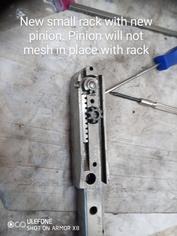
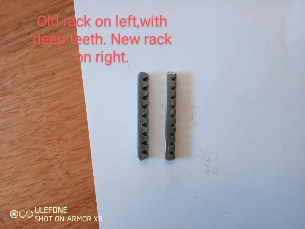
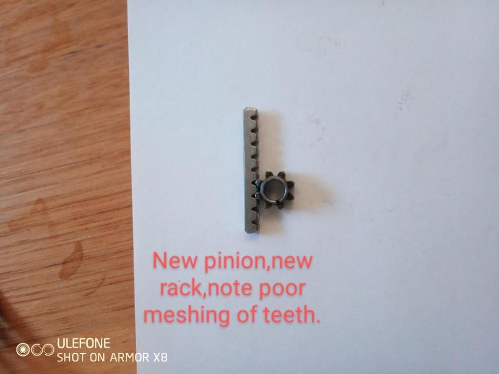
Thanks for the reply. It helps put in context what other people's experiences are with part fitment.I agree with buying all the parts together to aid the chance of matching. That is what I did when purchasing,even though the small rack looked fine I bought both pinions and both racks as I know from mechanical experience with motorbikes and cars,etc,over the years,that they will generally wear together,and are best replaced as a set if finances allow. That's why it was so disappointing when I received them, that teeth dimensions are all over the place. I thought when he assured me all parts were sourced ftom Taiking in Taiwan,that the parts would be a matched set.Not so! I understand that going from Singers version of imperial to metric would involve some discrepancies,but I would expect the teeth on the pinions to match the racks,coming from the same supplier. The racks slide fine in the grooves,the issues are all with the teeth spacings on the pinions,(although the small rack is lousy too if you can see it in the photos). Unfortunately,given the intricacy of the pinions, there's little I can do about the teeth. I'm fortunate that my brother is a fitter and turner/machinist, and has his own lathe and mill,though they are grossly oversized for the gears. We will try and skim a small amount of material of the underside of the drive pinion to stop it binding on the drive bush. The only other option is to try and drill the hardened casing on the backside,and thread and install a grubscrew to hold it to the shuttle drive shaft. I will stick with the "old" short rack,as it still seems in serviceable condition and is far better quality than the one I was sent. But what to do with the following pinion??? I have been thinking,given the light usage forecast for the patcher,that we may be able to mould some shim stock between the rack and the following pinion - to take out the slop. But again,given how small they are,this may not work. The other option is to keep buying pinions and hope one fits eventually. Before I bought this machine, I had never seen a patcher up close in person. I was so used to the size and bulk of the 132k and 133k that I thought it would be similar. It surprised me with how delicate it seemed, I guess thats the price to pay for getting into tight spots? But like all of these vintage machines,its a thing of beauty and engineering marvel and I intend to see it through. Regards - Andy. Ps: I don't blame you for holding onto the parts,haha.
-
Well,thats frustrating,typed out a lengthy reply, included a couple of Emojis and it wouldn't let me submit. So I'll have to start all over again. Did I mention I'm not tech savvy??
-
More photos,but need to resize
-
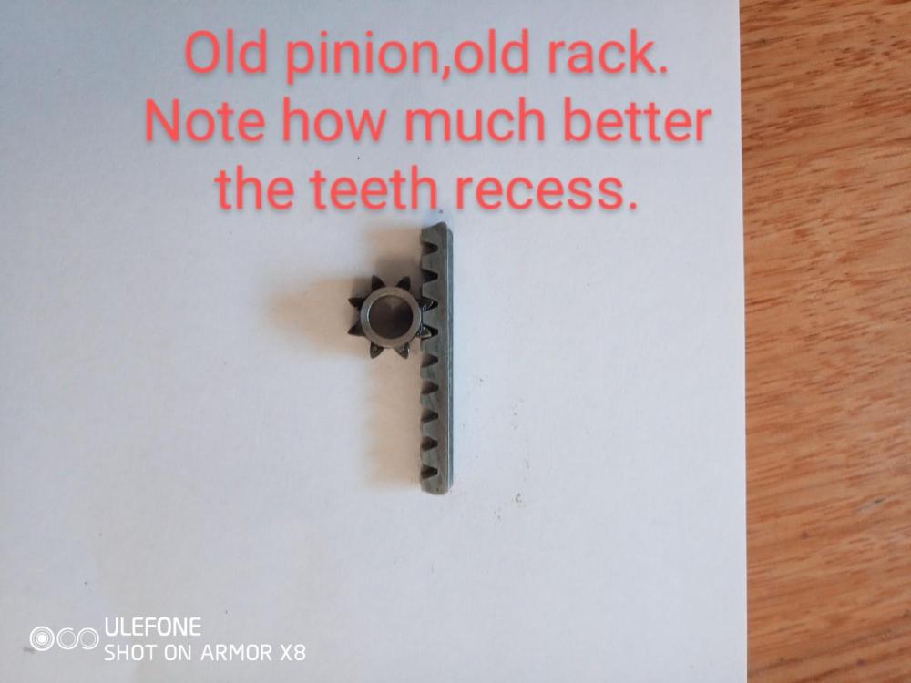
I have a group of photos I'll post to explain better. So, I rang the vendor and left an explanation message,no reply. I emailed him a lengthy explanation and sent all of the photos with details showing the issues, no reply. He has not called back or contacted me in any way, shape or form, seems to be avoiding me. So heres my dilemma, I'm now about $120 Aus out of pocket for dud parts and my project has stalled. I sent an email and photos/explanation,to Toledo Industrial off this forum,but have heard nothing back. What does everyone else restoring these machines do to access quality parts that are fit for purpose? I see from some posts I read this Morning,that Glen,aka Shoepatcher, may sell parts. Are you able to contact me please Glen if that's the case? If anyone can assist,please contact me,it would be much appreciated. Regards- Andy
-
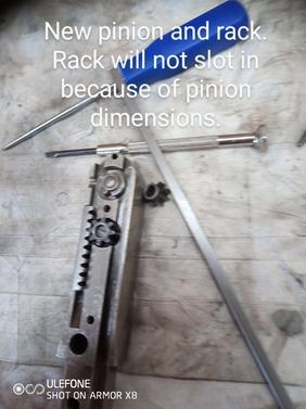
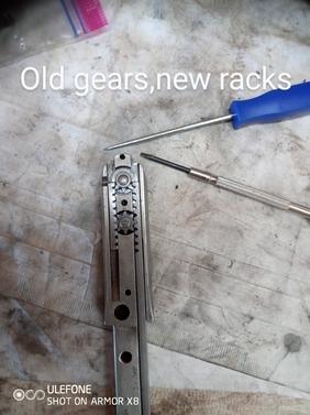
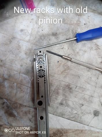
Normally the meat I removed would prevent the two from pulling so close together and binding,but I had no choice in trying to get the tapered screw holes aligned. No win there. The following pinion was next,the inner diameter was too small to fit on its post,yelling started about this time,the vendor's name was mentioned! I made a reamer from 400 grit wet n dry and a bolt,mounted it in the DeWalt and carefully removed enough do that it would fit its post and spin freely. With the old drive pinion in,I fitted the new long rack,it rotated the two pinions relatively smoothly. Where things got wierd was where I tried to fit the new short rack. There was no way that it would fit into the slot and engage with the pinion teeth. The old rack would not do so either. Both will fit nicely into the slot when the pinion is removed,both will mesh in a coarse fashion,with the pinion teeth outside of the gearbox. Both will fit in the slot and mesh with the old pinion,but it is worn. It appears that the bottom section of the pinion teeth are too narrow for the racks,though the large one will work. Measurements with the digital vernier shows minor differences all over the place.
-
The shuttle plate was so far off a basic reference point that after bouncing off the shed walls a few times,it went to the scrap pile. No more eBay s#@t. I then tried a supplier in Australia,he assured me his parts were sourced from Taiwan and were of good quality and fitment. When they arrived, I was quite excited, getting the gearbox back together was the last major hurdle and I hoped to give the 29 a test run shortly after. Unfortunately,his claims didn't stack up,the drive pinion had its tapered screw hole drilled marginally higher than the original and the holes would not properly align. So,I got some wet n dry emery paper and carefully took some meat off the bottom of the pinion shaft. i was now able to get the screw to go in about 3/4 of the way,but it now pulled the shuttle plate and pinion onto the bush, ( the 58 arm has had a simanco bush fitted, same as 71) and jammed them.
-
The problem I'm having,is sourcing quality consumables,springs,pinions,racks,etc. I started with an eBay order from one of the main Chinese sellers that appears to have sold alot of items for various machines. I ordered bush handle,springs, spare shuttle plate. The needle spring was too long,lacked spring and was too wide at the mounting point,would have required a dremel or filing to allow it to fit in the bore. The revolving bush handle was no where near spec,mounting holes were 4mm out and mounting flats for the bell crank were offset by 2mm to the footbar causing it to jam up. Tried modifying it by filing and counter boring holes but nothing we tried could get everything lined up as it should be.


