


Elmore
-
Content Count
39 -
Joined
-
Last visited
Posts posted by Elmore
-
-
The Barry King snap setter looks quite nice. I'll keep an eye on it as it appears to be out of stock at the moment.
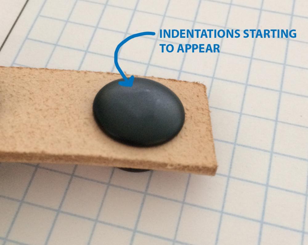
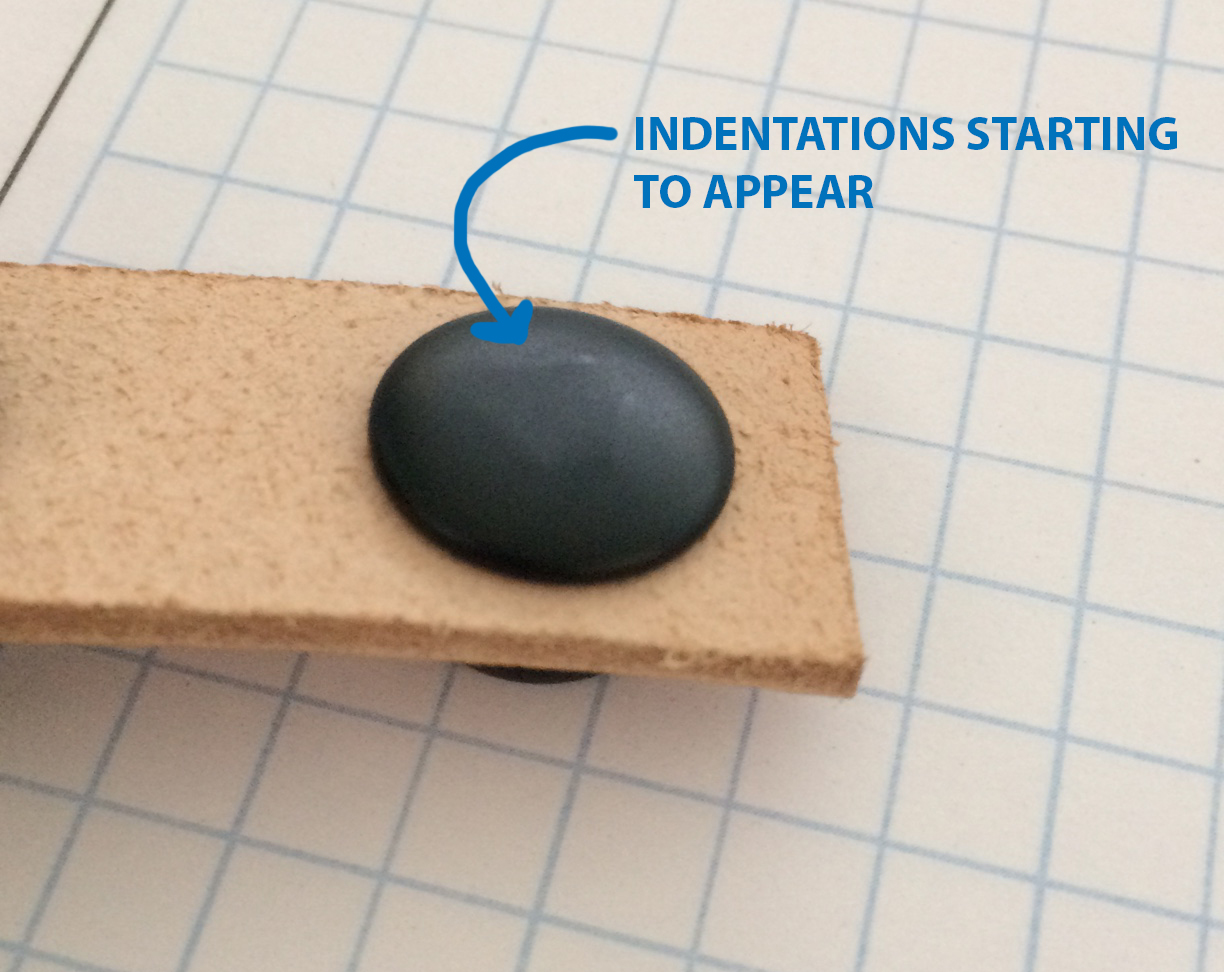
Dave - I believe the post is being driven into the dome as well, so as a test, I took a snap and put just enough force to begin rounding over the post lip. Then instead of finishing setting it, I flipped the post over, and could see the beginnings of the indentations in the domed surface. It almost seems like I need to support the dome of the snap around the perimeter, and leave it unsupported in the center. If I can find a likely o-ring, I'll test this idea.

-
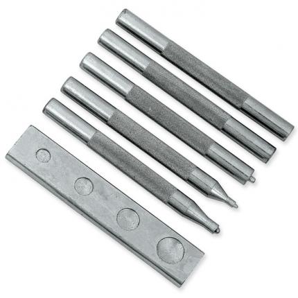
I've been setting line 24 snaps with the 1/2 ton Harbor Freight press + Tandy's snap/rivet setter set. A hole, in the ram of the arbor press, holds the Tandy setter, and rolls the post of the snap over nicely.
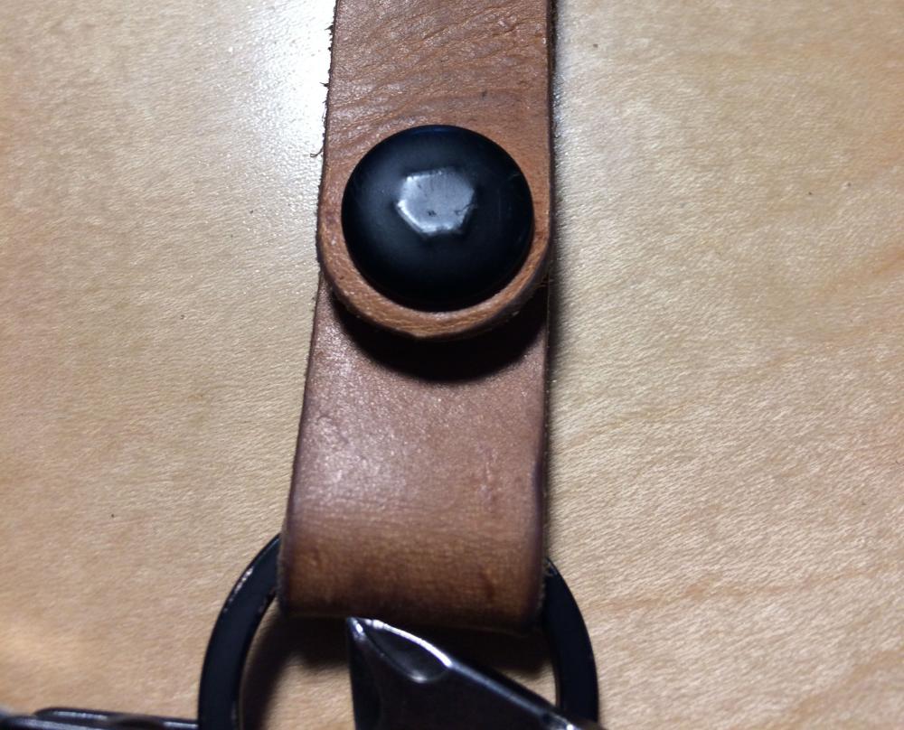
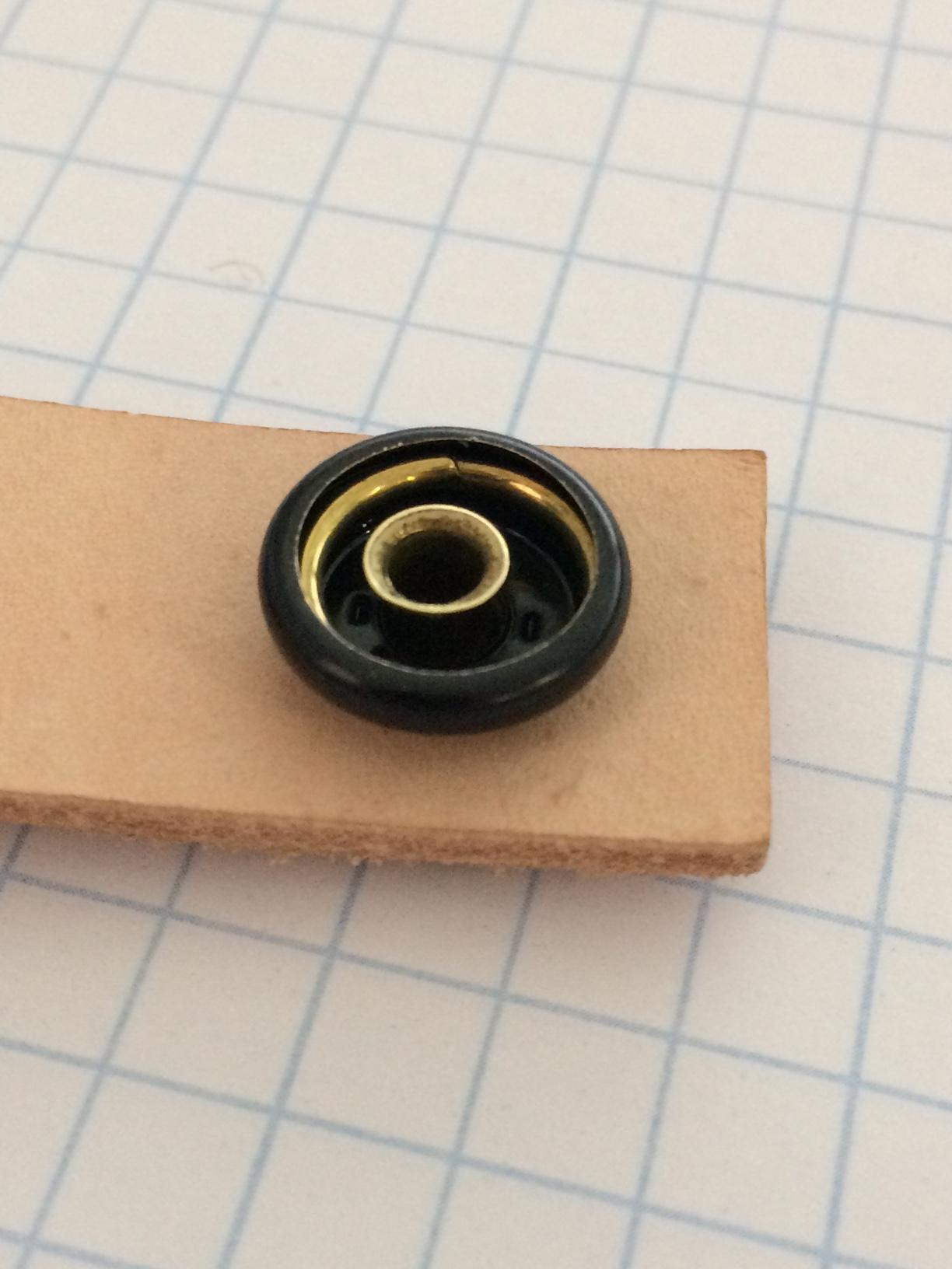
However, with some fancy new all brass Buckle Guy line 24 snaps, I've started to get some indentation on the domed top of the snap. It looks as if the post is being pushed into the underside of the dome, and causing it to deform. I trimmed a post down, thinking it might be due to excess post length, but it still had the indentation. This is on a single thickness of 4-5 ounce leather.
Any idea what's going on here? I'm tempted to buy Buckle Guy's snap setting hardware: https://www.buckleguy.com/bg-snap-setter-die-w-screw-fits-s15b51-snaps-requires-hand-tool-post-base-or-bg-hand-press/ and see if I get better results, but it doesn't look too much different from what I'm currently using!
-
Thank you for all the replies, this has been very helpful so far!
I like the simplicity of the bed mounted guide and the fact that additional cover plates are both readily available and affordable. I also can see how having the swing down guide would be beneficial in the circumstances Uwe mentioned. So I think I may pickup both and see which works best for me.
For buying a swing down guide, it looks like both in this thread are made by Kwok Hing. Constabulary posted a link to a UK site and UWE's is for Kwok Hing directly out of Hong Kong. Do any of the dealers in the US stock something like this, or do they have to be imported?
Uwe - it looks like you successfully tapped the head of your machine. Did you have to take any extraordinary precautions when tapping it? I've tapped plenty of aluminum and steel, but come to think of it, I don't think I have ever had to mess with cast iron. Thanks for posting your step by step photos of your fabricated bed mounted guide. That was a pretty clever reuse of spare parts!
-
I am seeking to learn about edge guides, and then purchase (or possibly make) one for my singer 111W155.
It seems like there are two different styles, one that bolts onto the bed or bobbin cover and is able to pivot away when not in use. The other bolts to the back of the machine and swings down. Both offer fixed guides as well as roller feet.
Other than the difference in price, with the swing down being more expensive, what are the benefits each has? Does the swing down offer much more versatility?
The bed of my machine has several tapped holes in it already, so it looks like a swing away guide was previously installed.

Thanks guys!
-
Thank you Bob! That did the trick. I never would have guessed that's what that access hole was for. The needlebar is now nicely centered in the throat plate hole.
Now to work on getting my needle and hook to be timed correctly.
-
Ok, so 5 is the lowest setting that's displayed on the wheel, got it.
I set the stitch length for 5 SPI, and it stitched the correct amount. So then I set it to 8 SPI, which also sewed the correct length. When I set it to 12 SPI it no longer ran true, that stitched closer to 14.5 SPI. I tried 16 SPI and that stitched 19 SPI. So it seems like the further from the 5 SPI, where I set it at, the more slop I have in the indicator.
I did take it back to 5 SPI after trying the 16 SPI, and my 5 SPI were not as exact as when I first set them. I can definitely work with it, I just wasn't sure how exact the stitch indicator is supposed to be.
Still trying to figure out how to position the needlebar within the throat plate hole.
-
Well, I finally finished my sewing table and have started going through the Navy manual for my 111W155. I've hit a few snags already, and thought it would be a good idea to ask a few questions before I chase my tail around in circles for too long.
1. In the manual, it indicates that the arrows on the timing collar and timing plate should be aligned when the thread take-up lever reaches the highest point. Putting the thread take-up lever in that position, I removed the connection belt from the lower pulley and advanced the lower pulley by hand. With the timing marks lined up, the teeth on the clutch pulley don't quite mesh with the belt. Sliding the connection belt back on, ends up retarding the timing marks by about 1/16". Is there a way to fix this?

2. Starting on centering the feeding action, I noticed the Navy manual said to set the maximum stitch length at 3 1/2 SPI. My 111W155 stitch length indicator has an engraved 5. However, I am able to depress the plunger and turn the balance wheel beyond the 5 indicator, but when I count the stitches, it's more along the lines of 4 1/4 SPI. Does a 111W155 have a 3 1/2 SPI indicator? Or is the furthest rotation point of the balance wheel supposed to be set at that length, and mine is off?


3. Lastly, I noticed that my needle is not centered in the throat hole, it's a bit too far back. Looking at the manual, it says to loosen the needlebar rock frame rockshaft connection crank pink screw (figure 4-7 [A], table 4-2). Which, best I can tell, is the only screw near the needlebar. Loosening that screw doesn't allow for any adjustment of the needlebar within the hole of the throat plate, it just lets me slide the needlebar up and down...


Any advice is well appreciated! I'm eager to get this machine up and running, but also want to take the proper time to get everything set correctly from the beginning.
Thanks,
Paul
-
Thanks guys, I will test a few more mount positions for the servo motor, and see which feels the best. And slap the hinges on to make sure the motor shaft centerline and the rotation point work together.
As far as the vbelt cutout goes, is there any functional reason to have it connect to the machine cutout?
-
I'm currently building a table top for my Singer 111W155. It did not come with an existing top, so I've been referencing images online. However, one thing I would like to get some more information on, is the distance between the server motor and the pulley on the sewing machine.
To position the servo motor lever that connects to the foot pedal roughly in the center of the table, I ended up positioning the motor 10 inches from the sewing machine (measuring horizontally, center line of pulley to pulley). Should the servo motor be closer to the sewing machine? Is a shorter vbelt preferable to a longer one? Currently I have a 3L400 on it.
In the image below, you can see the mockup that I've made with the 10" spacing. The socket cap bolts show the location of the servo motor. If I keep this configuration, it also seems like the vbelt channel does not have to be connected to the sewing machine cutout, which is pretty much how ALL the cutouts I've seen are.

Here's a diagram of my table top. There's an 1.5" tube steel frame inset 1.5" from the edge, indicated by the dashed line. The sewing machine is positioned 4" from the bottom and 7" from the right side, should leave plenty of space for the bobbin winder without running into the steel frame.

-
I've been carefully marking the default positions of pieces so that reassembly should be easy, but I wasn't sure how far into disassembly I could go before I started to affect something like the timing. I will probably not take it apart any further than where it's at currently.
Constabulary, I'm pretty sure this photo is of your very clean looking machine. This was the goal I was working towards in terms of cleanliness. Were you able to get it as spotless without removing a lot of the pieces?

-
Tejas, thank you for providing that link! That is by far the most readable one I've seen, and it looks like a very complete service manual. I'll add that to my growing collection of 111W manuals and leaf through it this evening and see what I can learn.
-

I'm working on disassembling and cleaning the sewing machine, but cannot figure out how to remove the presser bar (E.) and vibrating presser bar (H.). I was able to remove the presser bar position guide (A.) by removing the set screw holding it in place. This freed up the presser bar position guide lever (B.) to move freely up and down the presser bar. The lifting bracket (C.) can move as well, but seems confined to the channel where the hand lever normally is. The presser bar bracket (D.) is free to move as well. Looking at the parts list PDF, I'm guessing all these components must slide off once the presser bar has been removed. There are two other set screws at the top and bottom of the presser bar that go to the presser bar bushings that I loosened, but the bushings remained firmly in place.
Not sure where to go from here!
-
Wow Constabulary, that was beyond helpful! I will check the parts list to make sure the parts fit and get them ordered tonight. Thank you for the help!
-
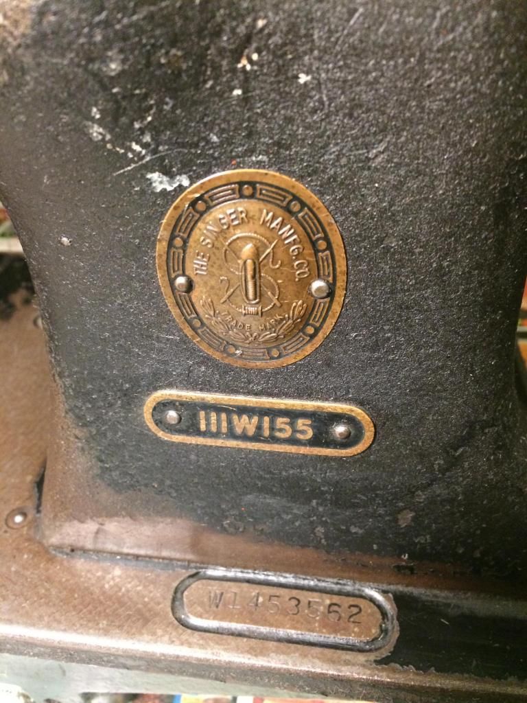
So I recently came by a Singer 111W155 that was used in a production environment. This is my venture into the world of industrial sewing machines and know very little about them. That being said, I’m pretty excited to get this machine back up and running.
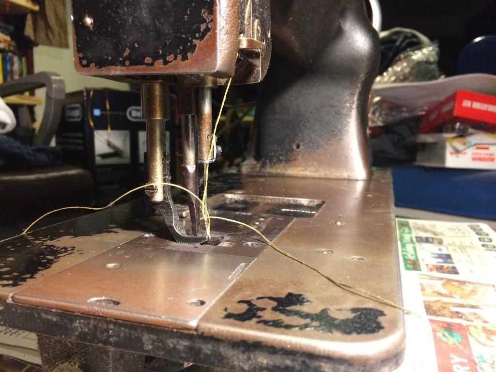
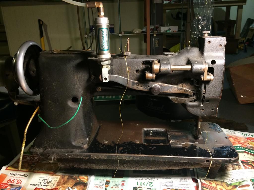
It did not come with a table, motor, bobbin winder, pedal, presser foot lever, and I’m sure several other things I’m overlooking. The presser foot lever has been removed and there seems to be some type of compressed air system in place. I’m not sure if there’s a way to manually lift the foot via a screwdriver but I would like to restore that functionality. If possible, add the knee presser lever I’ve seen on a few tables too.
I’m guessing getting it cleaned up is the first step. I was thinking I would give it a kerosene bath followed by some copious oiling. Is there a specific oil these old Singer machines like? Then I need to look into a servo motor, table, and all the missing attachments.
Looks like there are a few service manuals floating around the internet. Should go a long ways in helping me understand just what I'm looking at. http://navyaviation.tpub.com/14218/index.htm
Here are some pictures:
Front of Machine
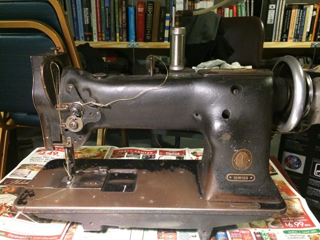
Model + Serial Number
Presser Foot
Back of Machine & Cut Wires
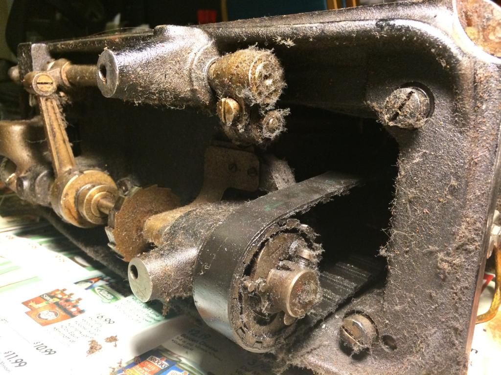
Gearing + Timing Belt
-
To wrap up this thread, I never did get to see the machine in the photograph. Instead, I ended up with a Singer 111W155 that had been pulled off the production line. I am going to create a new thread dedicated to getting that machine back up and running and post some pictures of it. It's missing quite a bit, but I think it is still worthwhile to get it up and running.
-
Unfortunately I do not have any additional pictures yet. I'm going to go see the machine in person on Monday and will take several more pictures then. Anything in particular to look for while checking it out?
-
Thanks for the information. It lead me to this video of a guy demonstrating a 111wsv71's capabilites. It looks like a pretty great machine.
-
Does anyone know what model Singer this is? I'd like to find a product manual, but need a place to start first.
Thanks!

-
I'll have to to give that a shot, it makes sense that the paraffin could be acting as a resist to the resolene. I've been using a a dremel wheel wrapped in cordura nylon that I spin against the block of paraffin to get nice and waxy and then run it along my edges. This results in a pretty smooth edge but nowhere near as shiny as I've seen on some people's work!

-
Hi guys,
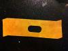
I've been trying to figure out a solution to the dye rubbing off of my edges. I make my edges following Bob Park's tutorial and use Fiebings Black Pro Oil Dye. After I dye the edges I buff them with a soft cloth until the black dye stops bleeding off and then burnish with paraffin wax. I then coat the edges with Atom Wax but have started using acrylic Resolene to try and seal the edge even better. Yet if I rub my fingers along the edge and apply a little friction I am able to get a black outline. Here's a picture of what I'm talking about (this was an early protype and the outline is not as prominent on successive ones but it does illustrate what's happening nicely!) Any ideas on how to stop it?

-
I will have to try some oxalic acid. For now I have been using a 50/50 mix of neetsfoot oil and paraffin wax that I rub in and set with a lighter/heat gun. Water beads on top of the leather and it has a nice matte sheen to it.
-
For this application I went ahead and diluted the mixture with a little more water and I sprayed it on with a spray bottle ensuring that the surface was uniformly covered as suggested by Katsass. Once it was dry I heated the leather and hand rubbed in some neutral kiwi shoe polish.
Overall it turned out much better than the previous pieces I worked on. But I did notice some small dark spots appeared on the leather, almost as if I sprinkled black pepper over it! Perhaps since I am using undyed vegetable tanned leather the specks are more apparent than if I would have been working with dyed leather.
Hopefully the specks can be seen in the picture I've uploaded. Any ideas as to what may cause that?
-
I mixed up a batch of Mop N Glo diluted to 50/50 and then applied it with a spray bottle to some undyed veg-tanned leather. From what I've read from the other forums about Mop N Glo it should be applied very lightly and at no more than two coats. So when I started to mist the solution on to the leather from about 18" away this resulted in the leather having a speckled look with the Mop N Glo appearing shiny.
To me it seemed like misting the solution on didn't cover all of the leather with the Mop N Glo solution and left some of the leather uncovered which resulted in the speckled look. But in order to cover all of the leather with the solution, I had to apply what I would call a pretty heavy coating.
So all you Mop N Glo people out there, how are you able to mist on the solution evenly in what constitutes a light coat? Other than the speckling I liked the overall aesthetic it gave.
Thanks,
Paul
-
I ended up tacking the leather on with a couple blued cut tacks and am pretty happy with the result. (I serendipitously created two little pockets that my threaded needles fit in perfectly so I don't have to worry about them falling and becoming unthreaded, pretty happy about that little accident.)
After sewing a few stitches on it I must say it works much better than the vise I was using previously. It was well worth the effort to finally build one of these! I'll try and get some pictures of the pony up in the next couple of days.


Pfaff 1222e (Not for Leather) Max Thread Size
in Leather Sewing Machines
Posted · Report reply
Hi all, I have a new to me 1976 Pfaff 1222e that I picked up for fabric and canvas work. This may be a longshot, but I'm hoping someone out there is familiar with this machine.
Should it sew #69 thread with a size 16/18 needle? When I tried sewing #69 thread, the stitches looked poor in comparison to stitches in a lighter weight thread. If it should sew #69 thread, I'll keep playing with the tension settings and see if I can't figure out the magic recipe.
The manual I found does show heavy-linen and denim paired with thread size 40 and needle size 90-100. Burlap is 40/110. Toldeo sewing chart converts that to #69 thread.
Thanks!