


Dave4
-
Content Count
44 -
Joined
-
Last visited
Posts posted by Dave4
-
-
It only took a few minutes.
A little give and take between the feed lift cam adjustment and the presser lift cam adjustment, and I think I got it pretty close to a happy medium. My foot is meeting the dog at plate level, and the dog has a more uniform rise - move back - drop motion, instead of the sloping up motion you see in the first vid.
My needle is "arriving" just after the foot meets the dog, which is correct according to the Seiko manual. Bob mentioned that the needle should arrive first (in fact it did in Video 2). IMO, that means the Seiko manual is probably wrong, but I ran out of time and patience chasing the elusive perfect setup, and I called it a night. I may play with it some more later, but it is sewing great now and looks pretty good to me.
Other noobs reading this: pay attention to when the needle comes up out of the material. The inside foot cannot release pressure on the goods until after the needle has cleared.
Big thanks to everyone here. I learned a lot today. And I made an adjustment that I haven't seen in any manual, and it worked.
Feedback and further suggestions always welcome.
Dave
-
So I grabbed a screwdriver and adjusted the feed lift cam. It is adjusted the same as any other cam, loosen one set screw, slightly loosen the other, continue to stab the screwdriver into the 2nd screw to hold the cam from moving, and advance or back up the hand wheel a little, then tighten the screw and observe your result by slowly rolling the machine by hand, making sure to stop immediately if something binds up.
In a few minutes, I had this:
You can see that now the feed dog motion is less of a slope-up and finish strong motion, and more of an even "almost rectangular" motion.
BUT - this feed lift cam adjustment messed up my prior presser lift cam adjustment. You can see that now the inside foot is "too late", not meeting the feed dog until the feed dog has already risen above throat plate height. After a few minutes of trial and error, it became pretty clear that both adjustments affected each other, and the optimal setting was to "balance" the two adjustments. So that's what i did.
-
I followed Bob's recommendation to adjust the presser lift cam. This adjustment is described in the Seiko manual, 2nd part of 8-12, or in the Navy manual, Chapter 4, page 4-7 - 4-8, available here: Navy Manual. Also described above by Bob and Floyd, with wise advice on how to not let the cam "jump away" when you loosen the set screws.
The next video shows the end result of me retarding that cam a little: the inside foot now meets the rising feed dog at throat plate height instead of below it.
Before I made this adjustment, my inside foot was meeting the feed dog before the feed dog rose to throat plate level (see the 1st video above). This squashed the material below throat plate height, which caused feeding friction and therefore inconsistent stitch length, but we never experienced the problem until we started sewing soft grabby garment leather. I guess firm leathers didn't get pushed into the low spot enough to cause drag or feed problems.
However, I still felt like my feed dog motion wasn't correct. It was still not rising to full height until halfway through the backward motion. About the time I finished this video, Uwe posted the post above this one, pointing out the difference between the feed drive cam (which I had already adjusted) and the feed lift cam, which I had never even considered because it's not mentioned in any Consew, Seiko, Pfaff, or Juki manual I have seen. Thanks Uwe!
-
Bob - thanks for the detailed response! I will start with your suggestions. I understand your warnings about not letting that shaft jump around during the procedure, thanks for posting them.
Floyd - thanks for repeating the warning. I did this adjustment once about a year ago. I learned then that the shaft will want to jump if you completely loosen both screws. It's possible I screwed it up back then. Time to check it again.
Bob - thanks also for the suggestion to adjust relative foot height. I've been doing this with the "Navy" method of setting relative lift equal (see image below). I will try it your way for fine tuning.
Uwe - You saw what I saw in the lift timing and action of the dog. The Seiko manual describes how to set the lift cam in your diagram: raise the needle 1mm from BDC, actuate reverse lever repeatedly while observing dog and needlebar. They should be motionless. If they are not, adjust lift cam until they are motionless while actuating the reverse lever. I've set and double-checked that adjustment according to the manual. This was the only feed timing adjustment I could conceive of, hence my questions in the OP. I'm going to start with Bob's suggestion, and then consider setting the lift cam "improperly" a little if necessary.
Gregg just posted while i was writing this. There is the manual. Thanks Gregg!
I'll post back what i find out.
Dave
-
I used the Seiko SM to set up our 206RB4-TH. It's been working well for canvas and 5oz firm leather.
We recently started some garment leather projects, and started noticing inconsistent stitch length problems.
Today I verified proper FD height, FD longitudinal position, needle centered in FD hole, and timing of the lift cam on the arm shaft (actuate reverse lever, confirm that FD and needle bar are motionless). I did all this according to the Seiko manual.
But I noticed that my feed dog eccentric motion doesn't look ideal. The feed dog is only at the proper height above the throat plate for half of the cycle.
I also noticed that the needle and foot are not arriving at the feed dog at the same time.
I'm pretty sure something is out of whack, but I can't figure it out.
Isn't the feed dog supposed to work in a nearly "rectangular" motion? Mine seems to be sloping up to proper height, which suggests a timing problem between the feed lift and the feed motion. Is there some other way to adjust the timing relationship of these two actions to get a more "rectangular" action, or perhaps I should be doing the lift cam timing adjustment differently?
Is the needle supposed to arrive at the goods at the same time as the foot?
In the attached image, #27 is a pinch screw for #24 feed rock shaft crank, which sets longitudinal position of feed dog.
#31 is a pinch screw for #30 feed lifting crank, which sets feed dog height.
#4 is a feed rock shaft base, also with pinch screws, but not mentioned in the service manual. When I acquired this machine, it barely sewed and a lot of the standard settings were "off". It's entirely possible that someone messed with this #4 base setting in the past, but I've never attempted do anything with it because it's not mentioned in the manual. Is this a possible culprit in my feed issues? Is there a method for setting it to a "factory" position?
I'm open to suggestions or ideas! Thanks.
.png.e88443bcf744bbc768fbd7a61923c317.png)
-
I was working on my 206 again today, and found so more info that may help others with snapping thread problem.
-
Thanks for the replies.
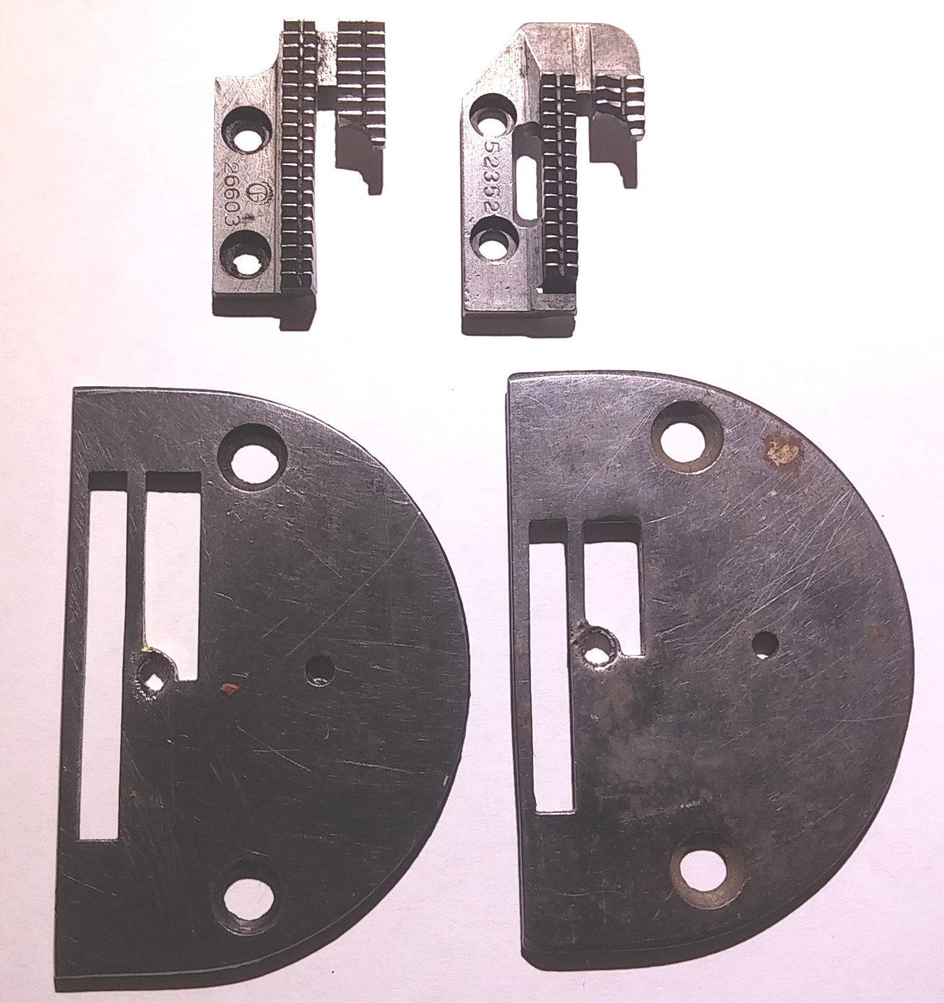
Searched around, confirmed it's mostly common sense:
Smaller pitch for lighter work, longer pitch for heavier.
Shorter row (tooth count) for lighter work and for curving. Longer row for heavier work and generally straighter stitching.
More rows for heavier material, also helps with straight lines, therefore not as easy to turn.
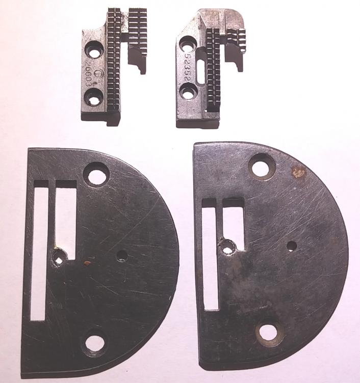
Singer 31 spawned a LOT of plate/dog combinations!
Thx.
-
Photo - other dogs with more rows and bigger footprint.
Compared to the dogs in the 1st post, what is the purpose or functional difference of the dogs in this 2nd post?
Thanks!
.png.85fe3ea6c90e0f9e3c72a096600a69a0.png)
-
Greetings all,
Photo: 2 feed dogs of different lengths.
What is the functional difference between the 2 lengths?
Is the shorter length better for curves?
Any other differences, such as intended for different fabrics, uses, etc?
Thanks!
-
Constabulary - I received your PM and sent you a reply.
Haven't heard back from you. May be interested in one or both, depending on shipping cost.
Check PM.
Thx.
-
I'm embarrassed to admit, we got so busy this summer I completely forgot I posted this question.
Any new purchases will probably be next year.
Thanks Constabulary and Uwe for the suggestions.
Constab - did you ever sell yours?
I see that the 130 has the classic crazing. I've never seeen a 130 myself that didn't have the crazing in the finish.
Thanks,
DCS
-
Greetings.
With the help of this board, last year I bought and restored a 31-15 and a 206RB4.
The 31-15 has turned into a favorite machine around here: it's a great stitcher and works well with light or heavy fabrics.
I'm considering buying another vintage industrial textile machine to restore and add to our shop. One with reverse!
We've gotten pretty good at flipping things around to backstitch on the 31, but we want reverse on the next machine.
What can you guys or gals recommend we look for in a vintage industrial that will sew light & heavy textiles, with reverse, with reasonable parts availability & prices?
Many thanks for suggestions!
-
Hello CD.
My set-up goal is to have the check spring release tension just as the needle passes into the goods, and to not pick up tension again until after the needle thread has been passed across the bobbin case face.
- Check spring stop too far advanced: lets off tension before needle tip reaches goods.
- Stop too far retarded: lets off tension too late after needle is buried.
- Stop just right: it lets off tension just has needle passes into goods.
My findings:
- When I set the stop just right, the check spring ends up with only a small range of motion, on pretty much all my machines. I guess that's normal?
- On my early 31-15, the takeup lever starts its rise before the needle thread has crossed the bobbin case face, causing snappy action instead of smooth action. I'd like to advance the hook timing, but the shuttle and crank are pinned on the oscillating shaft. I'm wondering if there is another way to either advance the hook or retard the takeup?
Thanks!
-
11 hours ago, gottaknow said:Once you get the stop set to ensure the thread is still taught as the needle enters the material, the torsion of the spring should corespond with the needle thread tension. The tighter your needle tension, the more check spring torsion. Sometimes you can find a happy place and it will accommodate different tensions.
Thanks Eric. This gives me a better starting point.
-
The best explanation I can find of check spring function is from the Navy manual: The check spring prevents the needle from stabbing into it's own thread by keeping tension on the thread until the needle tip buries into the material. Just when the needle eye reaches the goods, the check spring should land on it's stop, thereby relieving tension on the thread just as the takeup lever begins its down stroke.
If my observations are correct, the check spring should not enter the game again until after the hook has carried the captured upper thread more than half way across the bobbin face on its journey to becoming a lockstitch.
Once the thread has crossed the bobbin case face, the check spring should again take a load as the rising takeup lever pulls each knot tight.
If the only movement you see in your check spring is smooth up and down sweeps synchronized with the needle and takeup action, it's probably functioning correctly.
However, if you see the check spring making little jerking spasms at the start of each takeup lift, what you are seeing is tension loads on the thread at the very moment that the thread is trying to cross the face of the bobbin case. It shouldn't do this. Possible solutions: advance your check spring stop to reduce the range of motion of the check spring so that the thread has time to get past the halfway point of the bobbin case face before the check spring actually picks up any load. Or, slightly advance the hook timing relative to arm shaft timing so that the hook has time to bring the thread more than halfway round the bobbin case face before the takeup lever begins to pull the thread up. Or optimally, adjust both.
Check spring range of motion is determined by where you set the stop and by the relative position of the thread guides adjacent to the check assembly.
Check spring tension is determined by how much preload you set into the spring according to the adjustment procedure for your machine.
Assuming all of the above is correct, I guess I'm finally getting to my own questions. :-)
1 - My understanding is that you only need enough check spring tension to keep slack out of the thread during the check spring duty cycle (about half of every stitch). This means that check spring tension just needs to be pleasantly firm, not snappy taut. Is this correct? What effect does too much check spring preload have? What problems does it cause? Are there any rules of thumb setting check spring tension differently according to thread weight used or thickness of material sewn?
2 - I have recently been playing with check spring settings on a handful of household machines plus a 31-15 and 206RB. If I try to set these machines up so that the check spring lands on the stop when the needle eye hits the goods, and so that the check spring isn't trying to introduce tension before the thread has made it around the bobbin case face, I invariably end up with a stop setting that results in only a tiny range of motion for the check spring. Like a quarter inch total, or maybe 3/8" max. I must have it set in my head that the check spring should moving in a sweeping arc, not a small blip.
On rural roads, most oncoming drivers wave as you pass each other. Some lift their whole arm and do a nice big wave. Some barely lift a finger off the wheel (stingy wave).
My sewing machines all now have really stingy check spring waves. Is this normal?

-
Happy new year!
My 31-15 is from the 1915 serial allotment. Great machine, getting lots of use here. I installed a new race when we first got it. Using the Navy and Singer manuals, I have set needlebar height for proper hook timing. I have also tuned the feed dog height, position, centering and feed eccentric timing; and also done the presser bar guide lever set screw adjustment ( which I noticed has an effect on the check spring action because it changes the position of the slack thread regulator guide. More about that in another post.).
This machine is sewing well, but it isn't "just right".
My takeup lever has already started the upstroke before the hooked thread has passed across the lowest point of the bobbin case. So I have a mild snapping thread problem. It's not super-taut or bad, but you can see it and hear it. You can hear it lightly flick the bobbin case sideways every stitch.
I can minimize the problem by advancing the check spring stop CCW, but I can't quite eliminate the problem even if I adjust the tension assembly far enough to remove the check spring from service.
The shuttle driver and the crank are both pinned on the hook shaft, so a typical timing adjustment seems out of the question.
Is there another way to retard the takeup vs hook timing event on an older 31-15 that has the pinned shuttle driver and crank?
Thanks!
-
Excellent points Tink. Thanks.
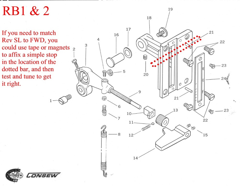
RB1 & RB2 could easily be modified by shimming the cover plate. This would be better than the magnet bar idea I suggested above, because once you got the correct shim in place, rev SL would = fwd SL across the full range of SL adjustment.
-
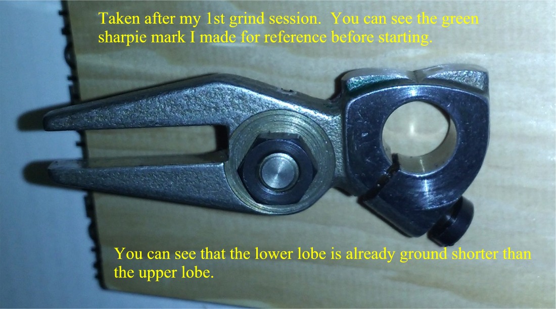
Thanks Uwe. You make a good point. One could lightly scuff and degrease the surface of the "short" lobe and then JBWeld a strip of shim metal to build it up.
Pro: this would simplify preservation of the original curvature of the lobe.
Con: it may be difficult to match shim thickness to exactly what is needed to equalize stitch length.
Theoretically, if you got it close, you may be able to make up the remaining difference by tweaking feet timing as has been suggested elsewhere, but I must confess that I had no success in altering SL with either suggested method of feet timing adjustment.
FYI for future readers, my reduction of lobe height was at least .065"; not a "small" adjustment. So if you try the glued shim method, you may need some hefty shim if you have SL variation of 20% as I did.
Wow that OP was long! I know that there are a lot of folks out there who own this class of machine, but I suspect not many of them keep a disobedient monkey, so perhaps I should have left that part out.
Best to all. DS
-
I've learned from Gregg's posts that RB1 and RB2 have a stitch length lever and push-up reverse. RB3-5 have a SL dial, and push-down reverse. RB5 has a dial lock tab. RB4 came in two series, Japanese TH series and a later apparently mixed SH series, some Japanese, some Chinese.
My Machine is a 206RB4-TH series. My reverse SL was shorter than forward. With the dial set on 10, the forward stitch measured 10mm, the backstitch measured 8mm. This 20% disparity persisted across the range of dial settings.
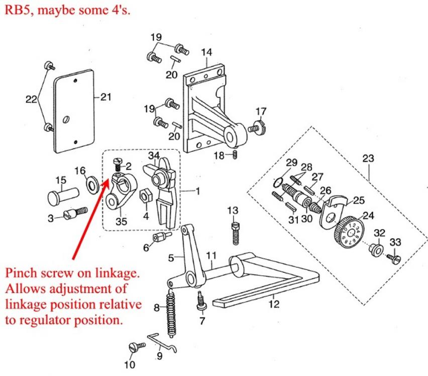
The Seiko chapter 8-13 Feed Regulator Adjustment procedure had no effect on my machine because my RB4 regulator pinch bolt is on the regulator itself rather than on an adjacent linkage, therefore the relational arrangement of regulator to rod cannot be changed. If you have an RB-4 or 5 with the later dual parts at the regulator rod, then adjustment of fwd vs rev SL is very simple, just loosen the pinch bolt on the linkage arm, slightly alter the relationship between the linkage and the regulator, tighten the screw, and see what effect you get. See drawings below.
Some RB4's and apparently all RB5's have a slotted feed rock shaft crank (FRSC), which would allow possible adjustment of feed regulation (and therefore fwd vs rev SL) at that location. If you have an RB4 that does not have the later dual part configuration, but does have the later FRSC, it is probably possible to adjust fwd vs rev SL at that point, but also probably possible to wreck something, so proceed with caution. My FRCS isn't the slotted variety, therefore I was unable to try this.
So I still needed to find a way to make this adjustment on my machine.
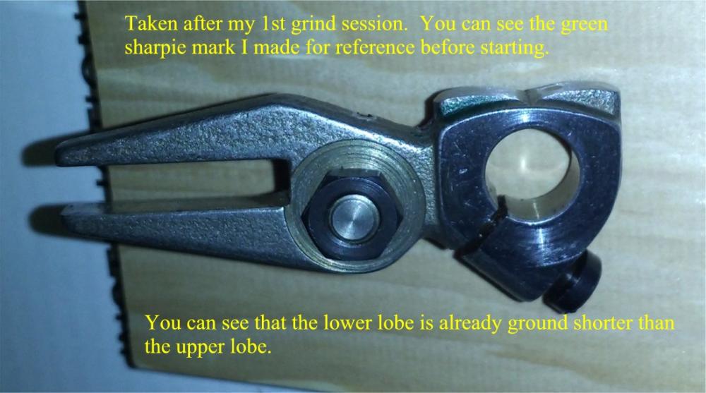
It has been suggested here that altering the inner presser foot timing can change fwd vs rev SL. According to the manual, this timing can be adjusted by advancing or retarding the lifting cam on the arm shaft. I tried that, with almost imperceptible effect on SL. Only a small range of adjustment can be made on this cam before the machine becomes inoperable, and it's a bear to attempt to make a tiny adjustment and then later put it back where it was. Be sure to make index marks with a sharpie before you start. I only recommend trying this adjustment if your SL difference fwd vs rev is very small. In fact, I don't really recommend it all because it attempts to later fwd vs rev SL by moving the machine out of a normal feet timing paradigm, which I suspect will impact machine performance in some way that will show up later.
It has also been suggested that altering the relative lift heights of the feet can change inner foot timing enough to change rev vs fwd SL. This is done by loosing the clamp screw on the lifting rock shaft (the slotted 6-sided hex nut on the upper rear of the machine) and advancing or retarding the shaft. This makes the inner foot lift height different than the outer lift height, and can therefore change inner foot timing, therefore theoretically changing fwd vs rev SL. I tried it, and it had no effect on my SL. I was okay with this outcome because I wasn't sure what the long-term of effect of sewing with irregular feet lift heights would be anyway. So I returned the feet to the equal lift height setting. BTW - the Navy manual Chpt 4 procedure for this adjustment is a neat trick and the easiest way to equalize the ift height of each foot. Pasted here:
a. Turn the balance wheel toward the
operator and observe the action of the alternating
pressers. If they do not lift equally, proceed to
step b.
b. Turn the balance wheel until the foot
that lifts too high is just above the throat plate.
c. Loosen the presser-lifting link crank
pinch screw (the same slotted hex nut I referenced above). The foot should
snap down; if it does not, push it down.
d. Tighten the presser-lifting link crank
pinch screw.
e. Repeat step a. If necessary repeat steps
b through d until the feet lift to the same height.Continuing, I also tried to equalized fwd and rev SL by changing the feed dog position, but that didn't work. I also tried changing the position of the reverse crank relative to the reverse lever, but that won't work because Screw 7 has a pin that engages a hole of the reverse lever shaft, permitting no adjustment.
I couldn't find any other method for fixing this problem, so i started looking at how the engagement between the feed regulator part and the SL dial rod worked.
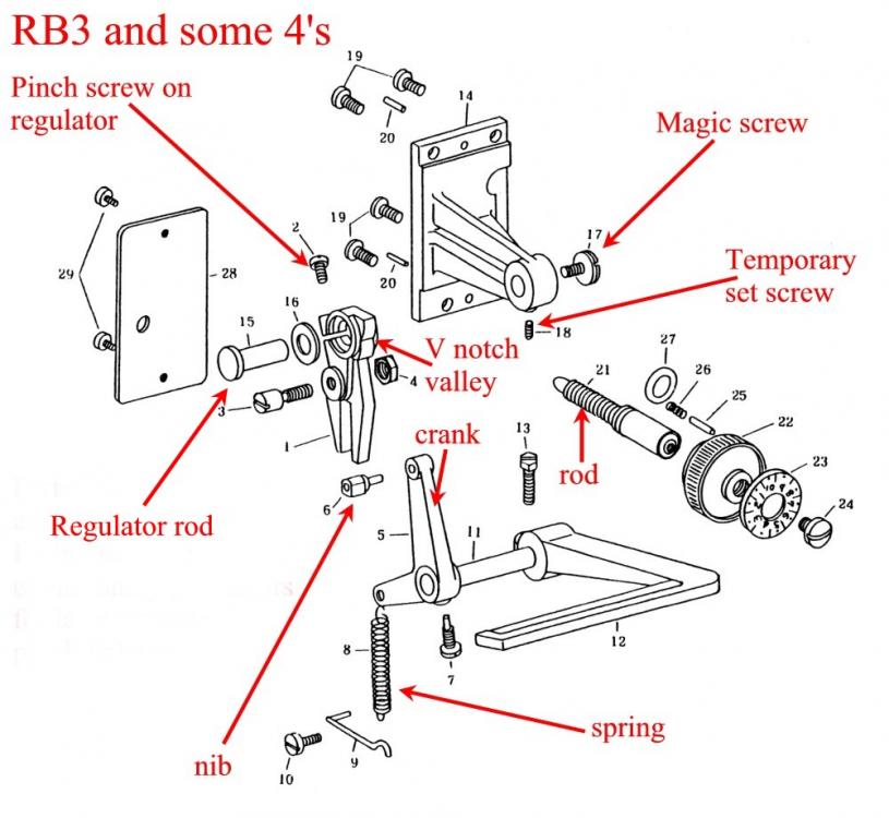
It's pretty simple. The regulator has a vertical V notch valley on its forward face that receives the rounded nose of the SL dial rod. This V notch has curved walls. It's a really shallow valley, perhaps it's more like two rounded lobes separated by a V. The reverse lever connects to an internal crank that engages the fork on the bottom of the feed regulator. A spring keeps constant downward pressure on the crank, which keeps constant forward pressure on the feed regulator, which means that the feed regulator is always trying to rock forward. The only thing that holds it back is the rod of the SL dial hitting the upper lobe of the V notch valley. When you turn the SL dial CCW, backing the rod out, the feed regulator rolls forward slightly (with the SL dial rod landing higher on the upper side of the V notch). This creates a longer feed action, therefore a longer stitch. When you press the reverse lever, this forces the regulator to rock all the way backwards until until the SL dial rod hits the other side (the lower lobe) of the V notch valley. In a perfect world, the two lobes of the V notch valley are of proportional dimensions that makes the reverse feed action the same as the forward feed action. Mine weren't. The lower lobe of the V notch valley on my regulator was too tall. When the reverse lever was pressed, the amount of distance that the regulator traveled was not enough to make the reverse feed action of the machine correspond perfectly to the forward action. It was 20% less travel than what was needed.
The solution: remove needle and throat plate. Remove the cast feed regulating base from the back of the machine, pulling the regulator out with it. It slides off the linking arm and pops right out. Take the regulator piece off the casting and grind down the lower lobe of the V-notch. This is basically grinding down a stop to allow more travel. Both lobes of the V notch are stops. The lower lobe was simply a stop that was too tall and therefore needed to be ground down.
I used a small sanding drum on a drill clamped in a vise, run at low speed. I oiled the drum for wet sanding. The critical aspects of the mod: Take a little at a time, test, repeat if necessary. Preserve the curvature of the face, so that rev SL will = fwd SL at all SL settings. Don't take too much off, else your rev SL will then exceed fwd, requiring a grind on the upper face of the V-notch to correct it.
When you put the feed regulator back on the cast base, use the set screw on the bottom of the base to lock the regulator rod temporarily while you tighten the magic split retention screw into the right end of the rod to hold the assy together. Procedure: gently bend the magic split open with a wedge, just enough so that it is almost too wide to be introduced into the receiving threads of the rod, tighten the bottom set screw to hold the rod still (the rod has a flat face for this), then insert the retention screw and run it in until nicely tight, then back it out 1/3 turn or so until the regulator spins just freely on the rod, then loosen the set screw, then place the assy rod-down on a flat hard wood block and strike the head of the magic split retention screw a good whack or two with a small hammer. The whack causes the screw split to spread so that even though the screw is slightly loose, it won't back out in normal operation. So you whack it hard enough to make magic, but not hard like you want to break something.
Get a helper for reassembly. Remove the throat plate! Remove the needle! The unregulated machine has maximum feed action, which will drive your feed dog into the limits of your throat plate or your needle into the limits of your hook if you don't remove them. Procedure: You have to insert the assembled base/regulator into the window, slide the linkage parts together, roll the machine slightly to find optimal fit for continued insertion, and you have to actuate the reverse lever up and down while poking at the nib that must fit and slide into the fork of the regulator as you slide the parts home. And you have to hold your tongue just right. The helper should not be a child unless the child is fully acclimated to an environment of choice profanities. The helper should not be your spouse or anyone you may wish to avoid offending. Probably should not be opposite gender, because then one gender will blame the other. If you have a monkey, and the monkey only does what you say half of the time, and the other half it does the complete opposite, then this will be a 6 second job and the nib will literally jump into the fork. The way i did it was to sit in a chair behind the machine and wear a headlamp and drink beer and stack layers of 3x3 plywood squares under the reverse lever to hold the lever at various positions and then got lucky. One time i got it in, then bumped the plywood stack and it fell right back out. It was great.
Test the result. If you didn't grind enough off the lower side of the V notch, take it apart (easy), grind more (easy), put it back together (yah). The grinding bit is an art, but hey, we're artisans right? Mine turned out perfect on the 2nd attempt. I sewed some cardboard without thread and measured stitch lengths and drank beer. Then I got up the next day and sewed more cardboard and marveled at how easy it was to fix the problem and how well it worked now.
If your rev SL is longer than your fwd SL, you'd grind the top rather than bottom side of the V notch valley.
When you finish a mod that alters feed action, you reassemble and roll the machine by hand with a needle installed and you go slow and feel for binding. Watch the extremes of feed dog motion within the throat plate slot. Make sure it doesn't collide. Make sure the needle doesn't hit anything in the bobbin area. If you are reasonably careful, there is no way your mod will cause the machine to exceed feed travel limitations, but the way to test that is by hand, not by motor.
If you have an RB1 or 2, and you have the unequal SL problems, I suspect you can solve it by rigging a simple external stop on one end of the SL slot. I've never seen one of these machines in person, but the parts diagram suggests that an external adjustable stop would be the simple fix for the problem.
If you have an RB4 or 5 that has either the adjustable feed regulator (pinch screw on adjacent linkage rather than right on the regulator), or that has the slotted FRSC, then you don't need this mod.
If you have an RB3 or 4 without adjustable regulator or slotted FRSC, then you can try to equalize rev SL to fwd SL by tweaking feet timing. If that doesn't work, you can buy a new regulator and see if it works better, or you can grind the one you have. I chose the latter option because there is no assurance that a new regulator wouldn't have the same proportional dimensions as the existing regulator. I suspect the regulator parts all have the same dimensions, and the common problem of unequal fwd vs rev SL is caused not by variations in regulator dimensions, but rather a variation in cumulative tolerance stack between machines.
Other: Slow wet sanding was effective. I only spent 15 minutes grinding, just going slow and careful. It was easy. The part appears to be case hardened, but light scratches are made fairly easily with the corner of a file, so the hardening is not prohibitively hard or deep.
Wow, this is long. I've learned a lot on this board. Hopefully this post is a way of returning the favor that may help someone else. Also hopefully, someone won't reply to tell me that all I needed to do was some simple thing that I overlooked before I broke out the grinder. We'll see...

-
OK, thanks to Wiz's suggestion, I gained a much better understanding of the check spring.
The combined available info from the 3 manuals referenced above is that the spring should come to rest on the stop only once the needle tip has touched the goods and the spring should "pause" while the needle raises as the thread passes the bobbin case. Based on that info, I set the stop in a position that turned out to be too low (too much throw) because my main focus was to be sure the spring was holding tension until the eye buried itself in the goods.
Taking Wiz's suggestion to "Experiment!", I learned to start watching the tiniest details in slow motion. I learned that the stop can be set to catch the spring just as the needle tip contacts the goods and when so, the subsequent takeup action will keep adequate tension on the thread until the eye is buried, even though the spring hit the stop a few microseconds earlier. I learned that the upper end of a grabby thread that is snapping across the bobbin face actually kisses the spring several times if the check spring stop is too low, which basically tensions the thread while it is trying to cross the bobbin face, which is bad. By fine tuning the stop, I achieved some improvement: the thread became a little less snappy across the bobbin face.
Note: my stop is now advanced almost to the limit, and my check spring throw is now quite short. I has a total sweeping movement of only 4-5mm, and only takes up tension when the needle clears the goods and pulls the thread up to cinch the lock stitch, and only holds tension until the needle tip comes back down to touch the goods. Other than the Seiko 0.039-0.078N spec, there is no frame of reference for setting check spring tension. Lacking the proper scale and linkage, I just played with mine until it seemed to match my overall upper and lower tension settings. When too loose, my knots were "fat". When too tight, it made the snapping sound of the thread across the bobbin louder, and it made the top thread lay deeper and tighter in the material, so it seems like too much check spring pre-load tension contributes to overall thread tensions.
Lastly, the tiny screw at the top of the discs warrants mention. One - the head on mine broke when overtightened, so don't do that. Two - loosening this screw allows you to rotate the discs slightly CW or CCW. The CW adjustment adds to check spring tension and action by moving the "passover finger" between the discs away from the vertical axis of pull of the takeup lever. This creates a slightly bigger additional corner that the thread must pass around as it routes between the discs and takeup lever, which equates to more spring action. CCW adjustment can move that finger completely out of the route, equating to less spring action, which is the way I went because my overriding goal was to alleviate the snapping across the bobbin face problem. All of the above helped, but didn't completely fix the problem, which was vexing.
Max linked the Uwe thread I had read earlier, where Uwe mentioned the timing relationship between the lowest point of the takeup lever and the thread crossing the bottom of the bobbin face. For the second time, i took Uwe's advice to confirm that this was happening, and yep, it looked pretty damn close, so I was still vexed, so i did a little more reading and noticed some careful language in Uwe's suggestions: "exactly" and "very".
He ain't kidding.
The takeup lever has a slight dwell at it's upper and lower extremes. My thread was snapping across the bobbin, crossing the lowest extreme of the bobbin during the dwell period of the takeup lever bottoming out. In slow-motion, I saw that the thread was arriving at the bottom of the bobbin at the end of the dwell period. The timing looked pretty good, but in fact there was just no margin left in the sequence and it was biased to being too late. Hope that makes sense. Focus on the word "exactly", and you may see what i saw on my machine. The hook was bringing the thread around a hair too late in relation to the takeup lever bottom dwell.
This brought me back to an original question in my OP: timing between arm shaft and hook drive shaft (as it is described in the Navy manual). They describe the process for the 225/226 type machine, which has a horizontal bobbin with belt drive. Obviously, the 206 is vertical bobbin, gear drive. My Seiko and Consew manuals don't mention "arm shaft to hook shaft timing" in the adjustment sections, so being the noob, it didn't register in my head until i did some more reading and (finally) realized that "Timing hook to needle" is the same thing. duh.
A little background: My machine was grossly maintained before i got it. It was well oiled, but nearly everything was out of spec, the latch opener was disabled, set screws were missing, others were loose, the lower gear case was cracked and near a catastrophic event due to a set screw floating in the grease, the feet lift heights were way different, the needle wasn't centered in the dog hole, the dog timing was off, the dog travel was off, the check spring was disfigured, the thread discs were flipped backwards, etc. It was a mess. BUT, one pleasant early discovery was that my needle eye height above the throat plate was exactly to spec (22.3mm) and the hook passed exactly 2.4mm above the eye, so that part was timed perfectly!
So why would i have to adjust that, right?
I guess the answer is because book spec's aren't always the exact settings you need. So to fix my snapping thread problem, I advanced the hook shaft to move the hook past the scarf, making it too "early". As follows:
I sewed 5 stitches in my test piece, left it in place, flipped the machine back, rolled it by hand to find which of the three set screws on the distal side of the clutch would be available when the thread was a 3rd of its way into its snapping journey across the bobbin face, rolled it more to loosen the other two, rolled it more to bring the offending thread into the snappy tight position just shy of the bottom of the bobbin face, then loosened the 3rd adjustment screw on the shaft and advanced the hook slightly by hand to bring the offending thread just past the bottom of the bobbin case (a mere 8° twist of the shaft), and locked everything back up.
Then I lowered the machine, removed the throat plate, and made the final hook-needle timing adjustment by raising the needlebar slightly to compensate for the earlier arrival of the hook. My eye height spec is now 23mm, my thread no longer snaps across the bobbin face, and the machine sews nicely.
Caution: if you advance the hook shaft too far, you move into a timing realm where the needlebar rock frame will no longer travel upwards enough from bottom to create a loop for the incoming hook, no matter how much you play with the needlebar height.
There are some things I still need to do:
1 - I need to go back and check the timing of the latch opener. It's driven by a cam on the hook shaft, and i advanced the hook shaft, so i will probably need to reset the fork on the opener shaft to restore the proper timing of the opener event.
2 - re-examine the CW / CCW adjustment of the thread discs, because i can now afford to have more check spring action.
3 - I need to get some tips on how to set presser pressure. I know how to turn the adjustment screw that pushes down on the bar spring, and i have just wheeled away on that thing with no real observable effect, so my problem is that I don't have any frame of reference for identifying when I have too much or too little pressure. Where do you guys start, and how do you know when you're "there".
Lastly, thanks to everyone who contributes to this board. In my younger days, I modified and raced jap bikes. 1 Honda, 1 Yamaha, 2 gsxr's and a gsx1300r. I service my own autos. I build small custom circuits. My hobbies led to my taking for granted the availability of comprehensive (even exhaustive) service manuals for technology. Then I got some sewing machines. It didn't take long to realize that comprehensive service manuals are not common companions of sewing machines. That makes this board a goldmine. Of late, I have been especially grateful for the contributions here from Uwe, Eric, Bob, Gregg, the Wiz, the Constable, and Art. I'm sure there are a few others, but having read half of this board over the last few months, and being over 50, I can't remember what day it is, much less everyone I read, so thanks to all!
Hopefully, my documenting my own learning curve in (too) long posts will be of some help to future readers. Pay attention to the E-words: Experiment, and EXACTLY.
-
206RB4 TH
I read the Navy SM Chpt4 and Consew and Seiko manuals, did all the adjustments in the Consew manual, also the feed adjustment from the STH8BLD3 manual, and also set the correct presser bar spring bracket height. My various timing specs and my latch opener are all good.
The machine sews well, but the thread snaps abruptly across the bobbin face instead of gliding smoothly over in a lovely poetic sweep, and I'm missing an occasional stitch.
I have tried lighter and heavier variations of upper and lower tension, with no apparent effect.
I saw a Uwe reference somewhere that mentioned timing of upper and lower shafts as a possible cause of this problem. The recommendation was to make sure the shafts are properly timed, but the machine in question was a belt drive. Mine is gear drive.
Unless I overlooked something, I can't find any info on timing upper and lower shaft on 206RB gear-drive machine. Is this something I need to check / adjust?
For a 206, what would be the most common causes of the thread snapping over the bobbin face?
Thanks!
-
Thanks Max, I think I have a can of 77 somewhere.
Correction: wife says it wasn't latigo. The piece in the photo was made using a sample given to her by a shoe repair shop, not the latigo side she's currently working with. My mistake.
DS
-
Hi, desk caddy prototype in attached photo. Wife made it as a practice/test piece, at the request of friend. Our 206 isn't quite ready yet, so she made this with 92 on a 31-15 with a teflon foot.
")
It's 5oz latigo and wool felt. She used whatever glue was laying around, and you can see how the felt wrinkled up when she formed it.
The piece is firm enough to hold keys, knife, wallet, etc, but still easily flexible by hand.
We need advice for choosing a proper adhesive that will hold the felt attached but also retain some flexibility.
We also need general advice on leather selection for this type of felt-gluing work; eg which leather types work best vs which should be avoided due to oils that might interfere with glue bonding. ie, is latigo generally a good or poor choice for this kind of work? etc
Lastly, do folks generally just glue onto the flesh side "as is", or is there a prep technique (sanding, shaving, roughing up, chemical treatment, whatever) that can be used to promote a better bond?
Thanks for sharing your expertise!

-
The Goldstar #4 grommet die is much larger than a "#4" grommet from the ebay press kit, but the Goldstar #3 grommet die fits the ebay #4 grommet perfectly, so one man's 3 is another man's 4.
Ah Kwok dies have a 19mm stud on the lower and an 8mm thread on the upper, so they can be run in the ebay press by removing the 12mm bushing from the press and inserting the die directly into the cast hole.


Questions about 206RB feed eccentric motion
in Leather Sewing Machines
Posted · Report reply
I have a "Bob sez" list of things I've cut-n-pasted from this site. It's a good resource. (Actually, I have 4 or 5 of these lists, based on comments from different tech contributors here.)
Anyway, Bob - I need to clarify which video you think was the best. I went back and renamed all the videos in this thread: Video 1, Video 2, etc. You can see the title in upper left corner of each one.
Above, when you said "I like the first vid the best...", did you mean Video 2, which was the 1st video I posted after I adjusted the presser foot timing, but before I messed with the feed dog lift timing?
Thanks.
Gregg - thanks for the additional manual. As Floyd already mentioned, it's surprising how often different manuals help clear things up.
Correct me if I'm mistaken, but I think the page18 procedure you referenced in the Juki manual is the same adjustment as Seiko 8-5, which is the yellow-colored cam in Uwe's picture, which controls when the horizontal component of feed dog motion begins and ends.
What I learned from Uwe's post is how to control when the vertical component of feed dog motion begins and ends by adjusting the timing of the blue-colored lift cam in his image.
What I learned from Bob (pending his reply here) is that a more "sloping up" feed like what is shown in both Video 1 and Video 2 can be a good way to set the machine up, rather than using the blue-colored feed dog lift cam adjustment to seek a more "rectangular" feed dog action.
Two more FYI comments:
FYI #1 - I used a good quality ruler to measure the horizontal distance traveled by the feed dog during the interval that it is significantly above the throat plate height. I set my SL to 3.5, and then measured how far the feed dog traveled while it was at least "halfway above" the throat plate. IOW, since my feed dog height is 1mm, I measured how far the dog traveled during the time that it was at least 0.5mm above throat plate height. Before I changed the timing of the blue-colored lift cam, the travel distance was 4mm. After I adjusted the blue lift cam, it was still 4mm. The only thing that changed was that instead of having a long slope up to a plateau and then a sudden drop-off, now it had a short slope up, a plateau, and then a short slope down.
This supports Bob's comments. Either way will feed the same amount. Bob gives reasons why "sloping" feed eccentric may be better.
My original feeding problem wasn't caused so much by a long sloping-up feed dog motion as it was caused by having the inside foot arriving to early, jamming the material down into the throat plate opening until the feed dog rose enough to push it back out
FYI #2 - In the OP, I mentioned the part #4 feed rock shaft base. I did a series of tests on this part. It had no effect on anything. My method: retard #4 a little, then advance #24 feed rock shaft crank the same amount. Test outcome. Repeat and test again. I did 4 iterations. I far as I can tell, an adjustment to #4 is the same as an adjustment to #24 - it changes the horizontal (longitudinal) position of the feed dog, but nothing else.
OK. Thanks again to all. Bob - shoot a quick reply when you have a minute. I gotta keep my Bob sheet updated.")
Dave