

Reacher10
-
Posts
9 -
Joined
-
Last visited
Content Type
Profiles
Forums
Events
Blogs
Gallery
Store
Everything posted by Reacher10
-
servo motor Servo motor with syncro and speed reducer
Reacher10 replied to Reacher10's topic in Leather Sewing Machines
Here are the files in STL, DWG (Autocad 2000) and DXF formats 30 tooth.dxf 30 tooth.stl flywheel.zip 30 tooth washer.dxf 30 tooth washer.stl rex flywheel dxf.zip sycro hub.dwg sycro hub.dxf sycro hub stl.zip rex flywhee stll.zip -
servo motor Servo motor with syncro and speed reducer
Reacher10 replied to Reacher10's topic in Leather Sewing Machines
Whoa... didn't see your post..... What format, dwg, stl, dxf or all 3. It will be the flywheel and the drive pully for 1/5 pitch timing belt and needle positioner hub. -
servo motor Servo motor with syncro and speed reducer
Reacher10 replied to Reacher10's topic in Leather Sewing Machines
Uwe, it looks like you are correct. The needle positioning did not work above a 5:1 ratio on either direct drive or with the speed reducer. I didn't check it at 5:1 exactly but it's safe to say that below 5:1, it works. The REX is setup at 4.8:1 direct drive and the JUKI is setup at 4.85:1 with the reducer and the NPS works perfectly on both. It looks like 5:1 is the cutoff point for the NPS. Hopefully this information will help others in the future. Thanks Rick -
servo motor Servo motor with syncro and speed reducer
Reacher10 replied to Reacher10's topic in Leather Sewing Machines
I knew that the sensor and the posi pin deal wouldn't work so that's why I made an adapter. If you want the flywheel and sensor adapters I'd be happy to make them for you. If you do, just count how many teeth are on the power wheel and I'll make it the same size. I am not sewing anything that's all that dense. I suspect that the JUKI will have more inherent torque in it's design compared to the REX so for the sewing I'm doing it shouldn't need a reducer. The whole deal with the reducer was that I saw how simple it was to make one...and I like making things...perfect fit . I know the servo motors run slow enough to have fine control of the needle position but it works so nice that for sure the NPS will supercede the reducer. Yeah...get a 3D printer...I'm 58 now and the technology that was around when I was a kid compared to what we have now is nuts! -
servo motor Servo motor with syncro and speed reducer
Reacher10 replied to Reacher10's topic in Leather Sewing Machines
I'm not sure how I posted 3 times...sorry about that. I figured a moderator would clean them out...thanks. Uwe, thanks for the input I'm modeling a 120 tooth pulley for the flywheel and I'll put a 20 tooth on the motor making a 6:1 direct drive. If the firmware is designed as you say then this will show if this limit is reached. I'm actually at 6.18:1 with the mish mosh of diameters I'm using now. If it does work I wouldn't even need the reducer since 6:1 should be just what I was looking for. However I could model the pulley's for 3:1 from the motor to the reducer and then again 3:1 form the reducer to the flywheel. So if the 6:1 direct works, it should work using the reducer. If it doesn't work at 6:1 direct I could drop it to 5:1 and so on. I know 3.6:1 (20 tooth motor to 72 tooth flywheel) direct works because that is what I've had since I put the servo motor on. I've been a mechanical designer for 25 years so I'm well versed in design, CNC, writing code and a crap load of other stuff. So the 3D printer is by far one of the coolest things I've owned. If your not accomplished with modeling, the problem becomes that you are relegated to models and STL files that you can find on the web or have it designed for you, my buddy has this problem. That's not to say that a person couldn't learn to model. There a a lot of modeling programs and tutorials out there, ya just gotta spend the time and stick to it. However being able to fabricate prototypes and real world parts is Joe cool! I fly RC planes and even though now a days we don't need to build our own air frames, there is still stuff that we need to fabricate. So now with the printer, I'm going hog wild making stuff. The problem I have with this big 120 tooth flywheel adapter is that diameter is right at the limits of how big of a model it can print...it's so damn close...we'll see. in the mean time the servo motor for the JUKI came today. I'll put the reducer stuff on hold and get the motor hooked up and see how it goes. -
servo motor Servo motor with syncro and speed reducer
Reacher10 replied to Reacher10's topic in Leather Sewing Machines
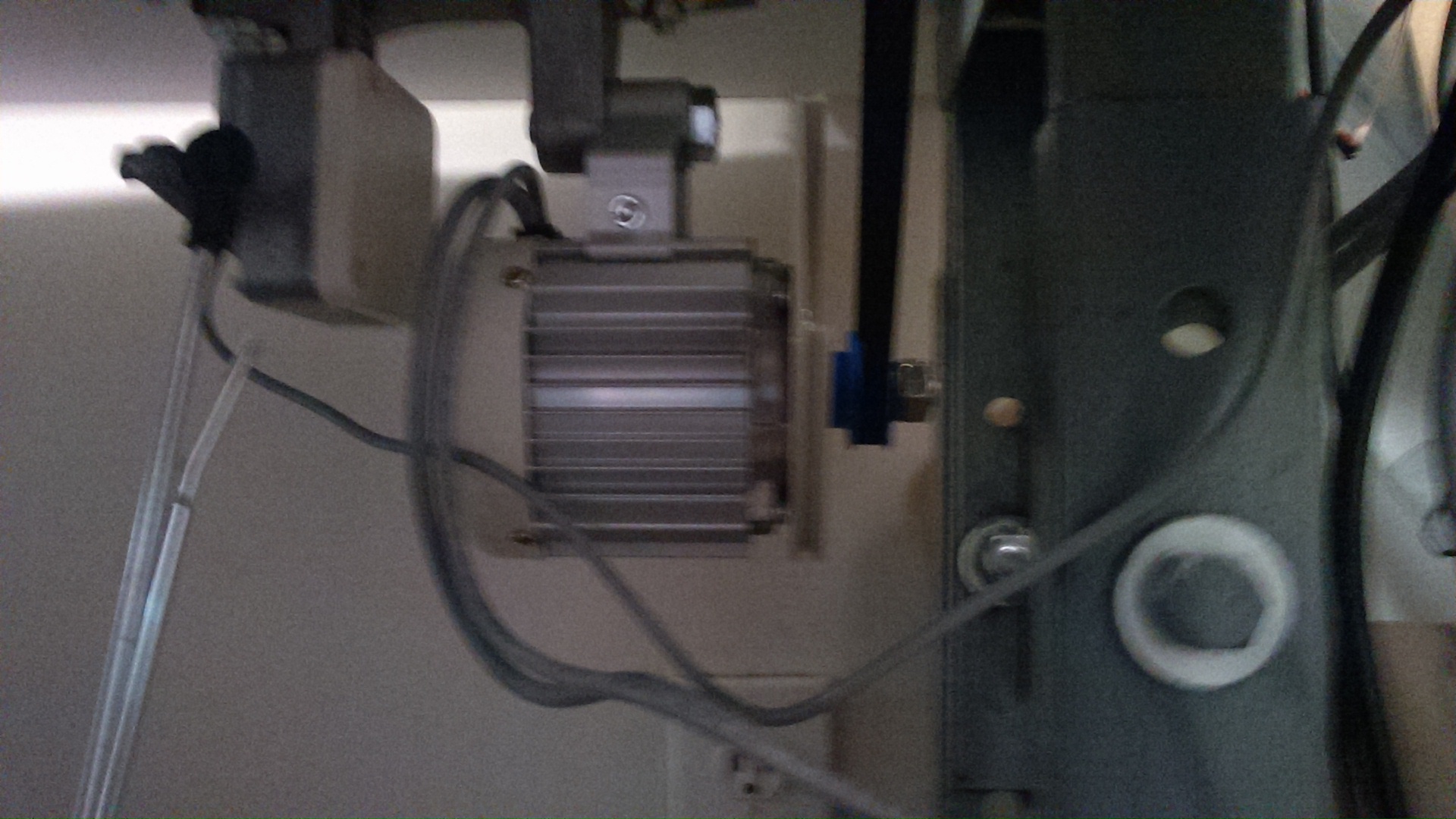
One more pic...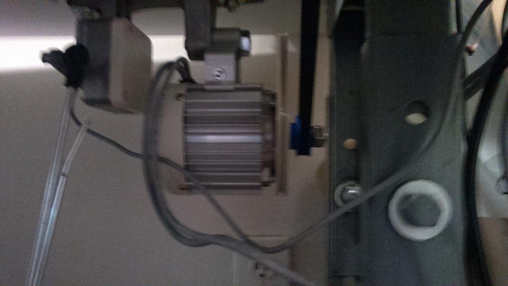
-
servo motor Servo motor with syncro and speed reducer
Reacher10 posted a topic in Leather Sewing Machines
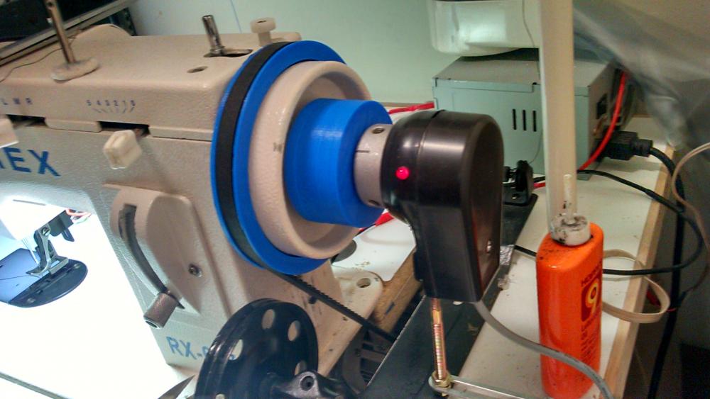
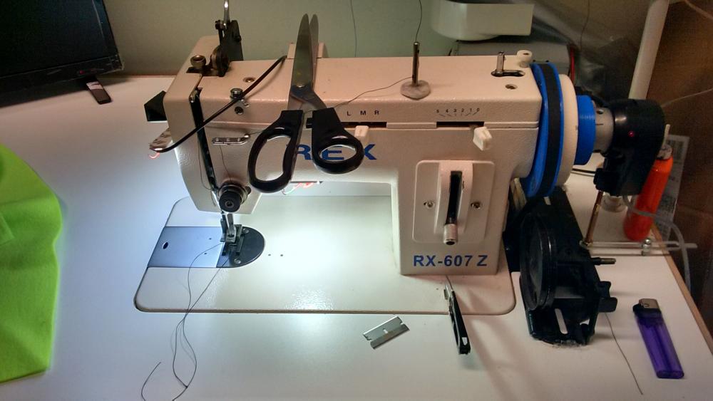
I have a REX 607Z setup in a custom table (had my friend CNC the top) so I could hook it up to a servo motor with a Syncronizer. The servo motor is brushless and has four buttons on the control unit, Consew CSM-1001. The machine is working absolutely great with the servo motor and syncro...it took the machine to a higher plane. Now this machine is very good for what it is however it will struggle power wise with the 550 watt motor, nothing major for the work I'm doing and nothing that bothers me...it is still light years better than the little motor it comes with. I picked up a JUKI 55 with the table and a clutch motor in good condition for $125. With how well the REX responded with the servo motor it was a no brainer to use the same brushless setup on the JUKI. Knowing that the 550 watt motor wouldn't have the same power as the clutch motor I bought pillow blocks and a shaft to make a speed reducer, I had a 2" and 6" pulley. My initial thinking was to use the 3:1 reducer with the clutch motor just to see if perhaps I could stick with the clutch motor if I indeed had better control. Well trying to deal with that giant motor just flat out got on my nerves so I said screw this, I'll just get the brushless/syncro setup for it as it would be much easier to deal with and in the mean time put the reducer on the REX. It would give me some extra torque and I could get the reducer up and running and get any kinks worked out. I did have to make a timing pulley for the brushless motor since the REX uses a timing belt. This was simple enough to do, I modeled up 30 tooth pulley for the motor and an adapter to increase the fly wheel to 5 inches...same deal as the power wheel sailrite sells. I made these on my 3D printer and away I went. Since I had the 30 tooth modeled for the motor shaft I just had to change the model to fit the 3/4" shaft for the reducer. Printed it out and boom, had me a nice reducer. It turns out I got it up and running in no time. Here is where the problem came in. The syncro was no longer working as it should. I have read reports of the syncro not working when a speed reducer was installed as well as reports of the syncro setup working fine. My initial thinking was that it SHOULD work correctly, thinking that the needle would go where it's supposed to based on the syncro. The total reduction ended up to be 6:1 and the servo setup doesn't know or care how this is achieved, like a 1" pulley on the motor and a 6" flywheel pulley. ...right?...wrong! I was perplexed by this. Well lets take a look at the numbers and I admit they are kind of all over the place. I put the original 70mm v-belt pulley back on the servo motor because the 6" pulley going on the reducer shaft was for a V-belt. The 30 tooth timing pulley I made for the reducer is 1 1/4" dia. What I discovered is that even though from the motor to the flywheel is a 6:1 ratio there seems to be a direct correlation between the revolutions that the motor turns and where the revolution on the syncro is. So the motor is spinning a 2.75" (70mm) pulley and turning a 6" pulley, that is a 2.18:1 ratio. Then on top of that I'm going from a 1.25" pulley on the reducer shaft to a 5" flywheel pulley which is a 4:1 ratio. So as I was about looking the positions of the drive pulley and the flywheel I realized the servo motor was turning a certain amount of degrees compared to how many degrees the syncro was reporting and they didn't add up! So if the needle position was simply based on the syncro postion then Bobs your uncle but because what the syncro reports and what motor reports don't jive, it ain't gonna work. So I'm not sure it will work even if I get the drive pulley diameters in line. A 2" on the motor to a 6" on the reducer and then from a 2" on the reducer to a 6" on the flywheel. The motor would be reporting 2 times the amount of rpm's than the syncro is reporting it should have....who the hell knows? I think I'll model and print the pulleys and flywheel adapter to those diameters and see what happens. Lets face it with the hodge podge of diameters I'm using now, yeah, that would throw anything out of sync...lol. As a test I made an adapter for the syncro to go right on the 3/4" reducer shaft and it worked perfectly. If anyone has any thoughts on this please feel free to chime in. For those that report no problems, my guess is that relationship between motor and flywheel rpm's does not apply on there control units. I'll post some pics of my reducer but right now it looks like 3 kids and dog had a wrestling match in there. Here's an FYI. On my unit, if I set it up for needle down I can additionally press the back of the treadle and the needle will raise. However if I set it for needle up, when I release the treadle. that's it, needle up, no needle down option. So what I do is set the control unit for needle down but the needle is up and the syncro is set to report that it's in the needle down postion. When I release the treadle the needle goes to the up position but then if I want the needle down i just press on the back of the treadle....it works great. Stay tuned... BTW...first post...I've learned A LOT form this forum...THANKS!