Kryptonite
Members-
Posts
51 -
Joined
-
Last visited
Content Type
Profiles
Forums
Events
Blogs
Gallery
Store
Everything posted by Kryptonite
-
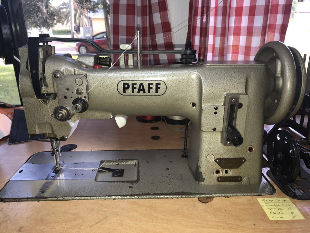
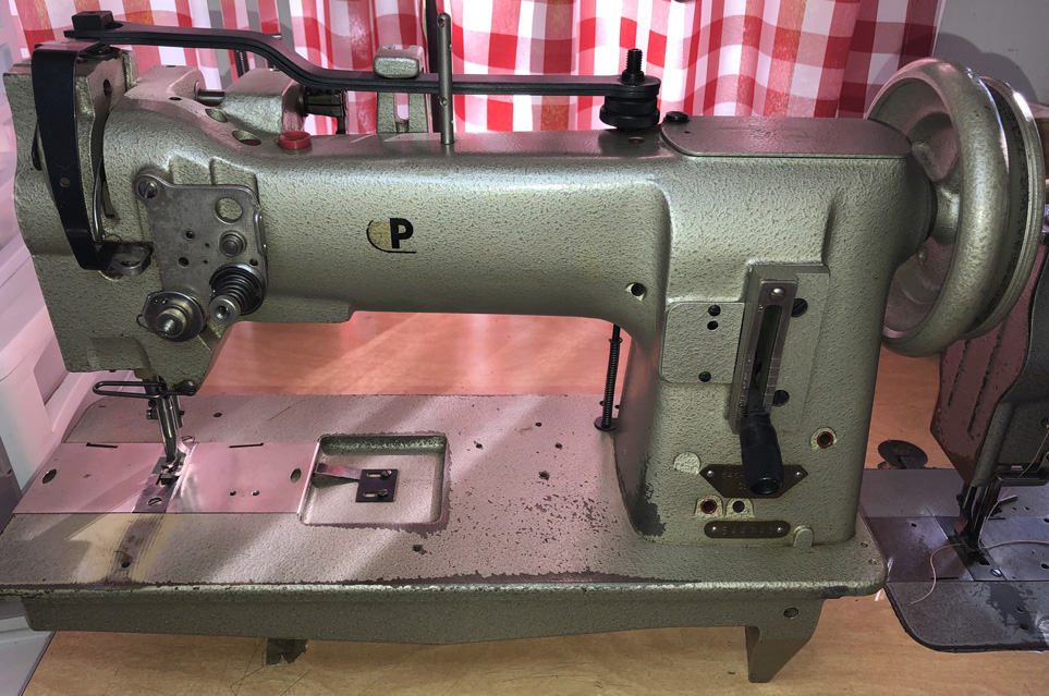
Hi Guys, I have a beautiful low mile Pfaff 545 H3 that I final got hooked up to sew garment leather. I'm having a problem with the thread pickup level pulling the garment leather up about an 1/8+ inch at the end of it's stroke. So when I am sewing along the edge of 2 layers of leather, this lift is enabling the needle to miss the top layer of leather on the downstroke, ruining my stitch. The foot/presser timing seems to be good. The needle and the inside presser, and the feed dog hit the product at the same time. I checked my Consew 206RB-02 and there is just a hint of product lift. This to me says something on my Pfaff is not timed right. Can anybody shed some light on why the take up lever is pulling my product up? I can post a video if needed. Thanks, Will in Central Florida
-
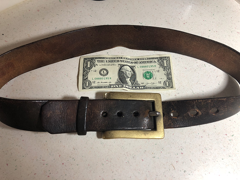
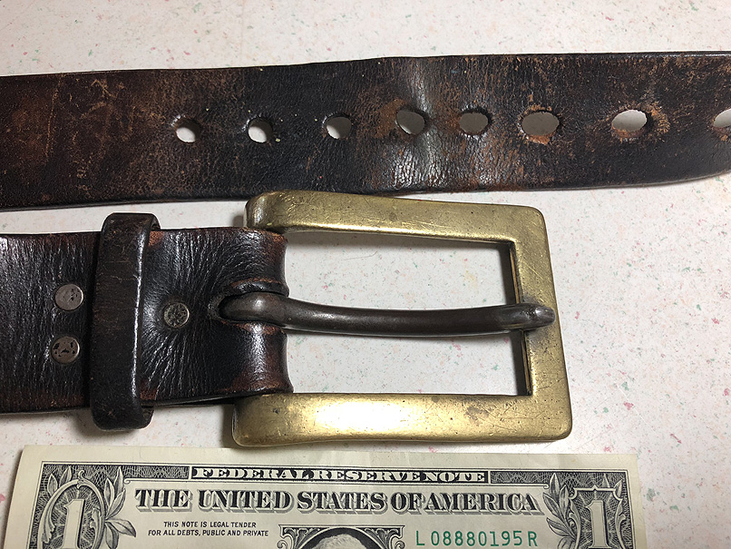
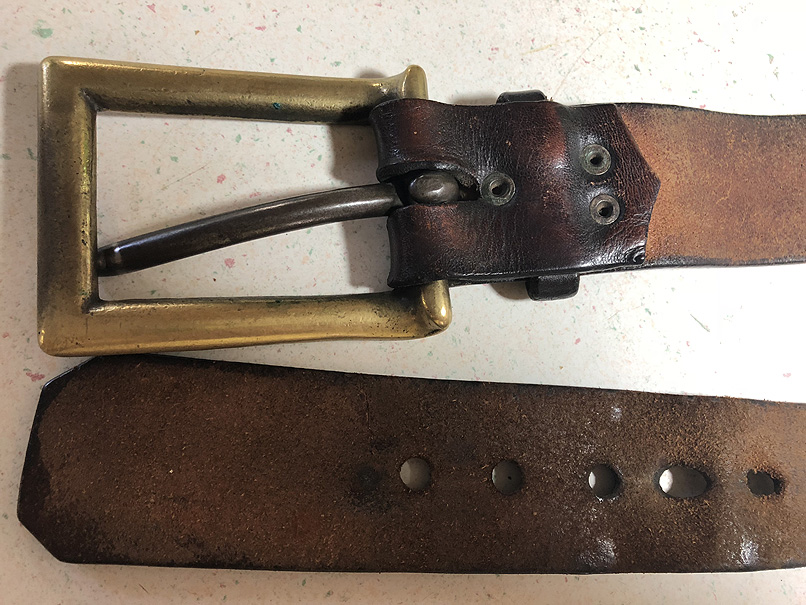
Hi Guys, I've had this odd belt for a while, I think I paid $2 for it at a local flee market in Florida, and I've never seen anything like it before. The buckle and the tongue are huge. The tongue is almost the diameter of a standard pencil. It is undoubtedly old, it could be really old. Can anyone shed some light on it's vintage/origin or possible history? Was it George Washington's? LOL Thank you, Will in Central Florida
-
Consew 226 Stitch Selector Not Working
Kryptonite replied to Kryptonite's topic in Leather Sewing Machines
Ok thanks guys, much appreciated! Will -
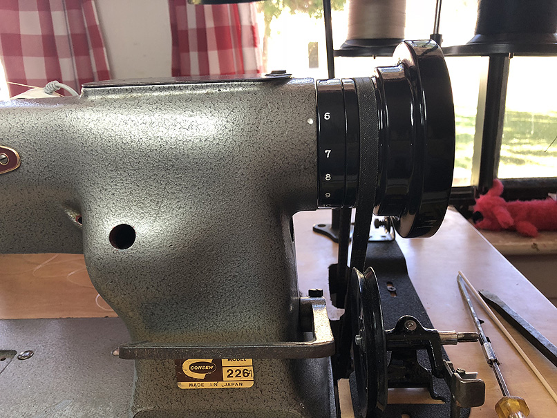
Hi Guys, I have an older Consew 226 that sews well but the stitch selector is not accurate. I loosened set screw on the selector ring and set it on "5" and I'm getting stitches 5 per inch. Ok great. Then I go to "10" and get 8 stitches. I select "12" and I get 10 stitches - you get the idea. Something must be out of adjustment. I have searched but I can't find info on this particular selector type. Can someone point me towards a fix? Thank you, Will in Central Florida
-
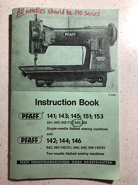
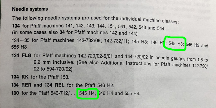
I have a Pfaff 545 H3. The owners manual clearly states the H3 uses the 134-35 system and the H4 uses the 190 system. My H3 that I bought last week is using 190 needles. I plan on using 138 and 207 thread so I need to get some larger needles. Do I stick with the 190 system or should I go to the manual recommended 134-35 system and adjust the needle bar? Would that be the only adjustment that required? Thank you, Will in Central Florida
-
pfaff 545 145 Pfaff 545 Foot Movement Isues
Kryptonite replied to Kryptonite's topic in Leather Sewing Machines
Uwe you were absolutely right. There was not enough pressure on the front foot to enable the outside foot to lift. Thank you so much for the video. I followed the steps you outlined and now my dancing like they just left the factory. I looked at the hook timing and the hook is just missing the needle in the middle of the scarf... I think I'm in business. I am hoping to run some thread through the machine this weekend to see if it sews. Thank you again for taking the time to share your knowledge. You help make this Forum great! And I'm sure many people will benefit from the video as there is not much information about the Pfaff 545 foot timing. Cheers, Will in Central Florida -
pfaff 545 145 Pfaff 545 Foot Movement Isues
Kryptonite replied to Kryptonite's topic in Leather Sewing Machines
Ok I think I figured this out maybe. I have 2 pressor tension leaf springs running along the top of the machine. If I remove one spring the outside foot seems to be walking. So if that is the fix... why does the parts manual show 2 springs (661 - 662)? Maybe something pertaining to the knee lift operation? My machine head is not mounted in the table right now. Cheers, Will from central Floida -
pfaff 545 145 Pfaff 545 Foot Movement Isues
Kryptonite replied to Kryptonite's topic in Leather Sewing Machines
Got it :-) Presser Vid... -
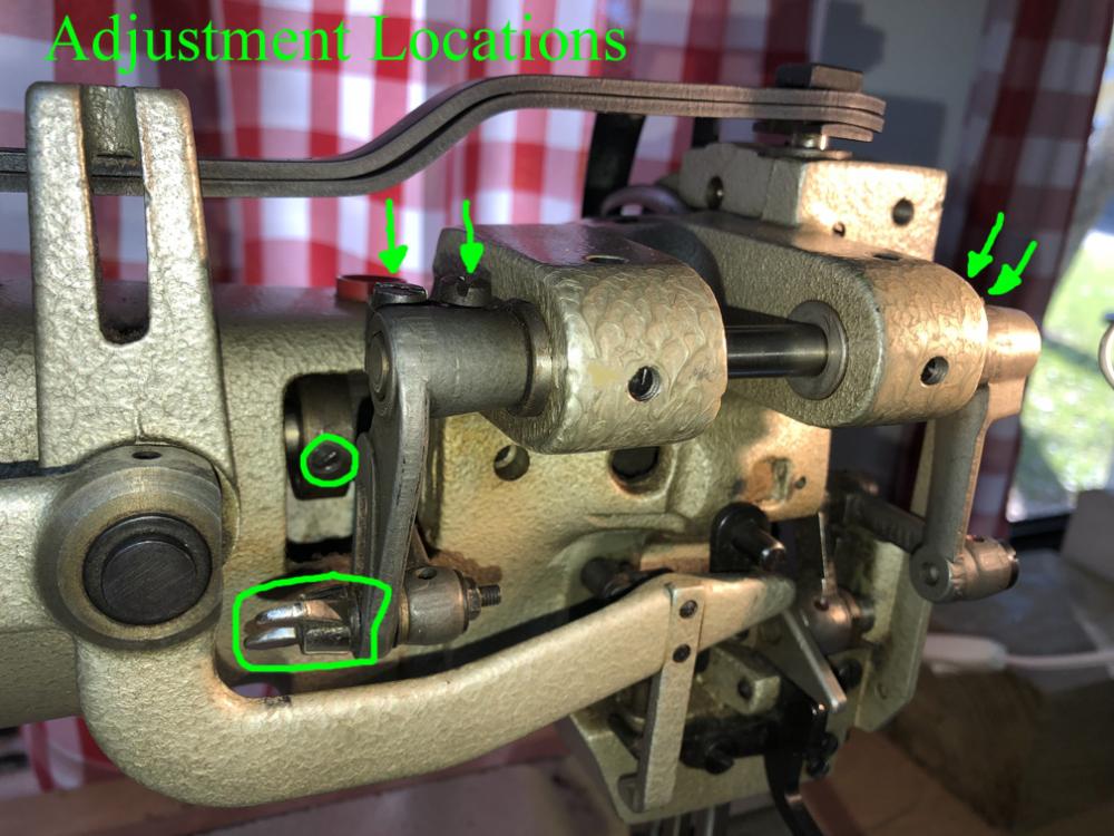
Hi Guys, After having fun with my Singer 111W155 Rehab a few months ago.... I thought I would try it again. I purchased a Pfaff 545 H3 with motor/table for $100 because it would not sew. I figured it looked pretty good and chances are it could be fixed. It had at least 2 issues. The Safety Clutch had popped, which I reset. Second was the 2 pressers feet where not moving right. The Inside sort of looked ok. The outside foot was not moving at all, and its lowest position was 1/4" or so above the needle plate. I found the 2 screws that hold the presser bar in position and lowered the outside foot to touch the needle plate. After playing with the adjustment screws, as noted in picture below, for 2 hours trying many combinations I still could not get the outside foot moving at all. Could a Pfaff expert suggest a solution? Thanks, Will in Central Florida
-
I can turn my handwheel enough to move the needle/stitches without to much trouble, but it is stiff. A little less belt tension might help you get some pressure off the handwheel so it will move for you. I would at least try that. For multiple hand stitches I have been lifting the head and removing the v-belt. Auto V-belts work ok. I just happen to have a Sailrite 6 pound handwheel. Mounting problems aside, I don't see it as an fix. You are still going to have the high belt tension and now even more weight to start rotating, more force required. Cheers, Will in Central Florida
-
A shout out to Bob at Toledo Ind. Sewing for making this great reducer pulley. I can slow a stitch to an absolute crawl. Will
-
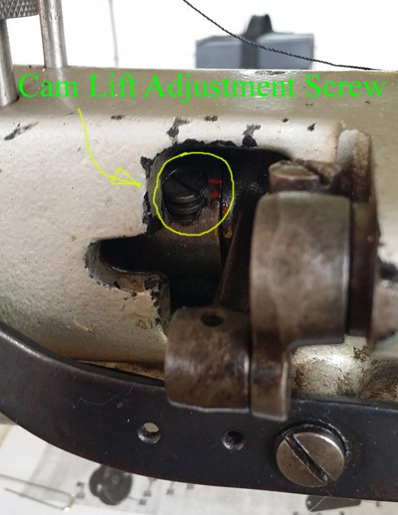
Jimi, great tip on straightening the pins from the inside. I'm going to try that! Cbm, did you get it working right? If not, try this... Your presser foot lift height is controlled by the Eccentric Cam LIFT or wobble. Regardless of the position the Cam sits on the upper shaft, adjust the Cam LIFT to a middle position within it's range of motion. The LIFT can be really high to zero (actually negative), so figure out how it moves and put it in the middle, i.e. +5 out of ten. There are 2 screws used to adjust the LIFT. One is a lock screw which you can remove for the adjustment, and the other adjusts the LIFT of the cam by turning it clockwise or counterclockwise. Count the turns and put it in the middle. That should get it about right. In my case it was perfect, dumb luck with just one adjustment. From a design standpoint you have to figure Singer would machine a cam with the same range of adjustability both above and below the ideal LIFT position so that is a good place to start. After the pressers are lifting the right amount then time the middle presser with the needle to land on the product at the same time. This is done by rotating the Cam on the upper shaft. Two Setscrews hold it in position on the shaft The Pinch Screw is used to equalize the inner and out presser lift - so the feet are lifting the same height. Hope it helps, Will in Central Florida
-
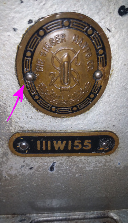
Thanks D I'm thinking ahead to the day when I start on the cosmetics. What is the best way to remove the brass badge pins? Will in Central Florida
-
Great! Bob as you kindly suggested, I started with the Presser Lifting pinch screw, trying to balance the inside and outside foot lift. After that it was evident the needle and the inside foot timing was way off. The only thing I could see that would change the timing was the location of the Presser – Lifting Eccentric Link on the upper main shaft. So I removed the Setscrews from the Link through the access hole, neither of which were "pointed". Holding the Link in position, I turning the handwheel just barely getting the shaft to move. A little at a time I rotated the Links position on the shaft until the needle and the inside foot landed on the product at the same time. BTW - after each little move of the Link I looked in the Setscrew holes for a groove on the main shaft (Simanco #240360) and none was to be found, and no visible “S” stamp on the Link. Next I adjusted the lifting height of both feet with the Eccentric/Cam - the more "wobble" the higher the foot lift. Then back to the PL pinch screw a few more times for fine tuning. Interesting engineering. So I’m glad I can move on to check the needle/hook timing using Uwe’s great vid, and am grateful for all the help I am getting. To summarize for the next newbie… The Presser Lifting pinch screw - adjusts the lift “balance” between the inside and outside pressers. The position of the Presser Lifting Eccentric Link on the upper main shaft – times when the needle and the inside presser touch the product. The lift (wobble) of the Eccentric/Cam Link – determines the height both pressers lift. At least for my 1950’s Singer 111W155 version, others may differ. Cheers, Will in Central Florida
-
Guys is this right? Thanks, Will
-
Thanks Dikman post and the tips. More later... Will in Central Florida
-
Here is a video of my shuffling foot action. I think I need to move the Presser - Lifting Eccentric Link but it is stuck on the upper main shaft. Any suggestions to fix this would be appreciated. Will in Central Florida.
-
Concerning the Presser-Lifting Eccentric link with the 2 setscrews on the upper main shaft, the military service document says to loosen the 2 setscrews, hold the link, and turn the hand wheel changing the position of link on the shaft. When I loosen the setscrews I still cannot get the link to rotate and change position. Before I really put some muscle behind this, and possibly mess things up, I would like to ask for advice. Is there something else restricting rotation of the link? What am I missing? Thanks in advance. Uwe your vids are great, a BIG help. Will in Central Florida
-
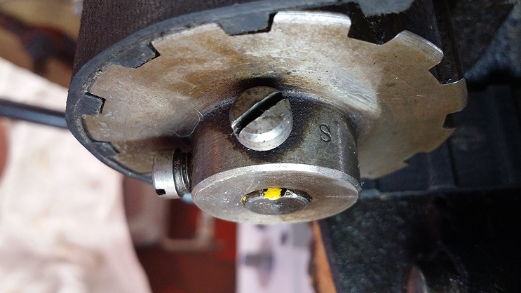
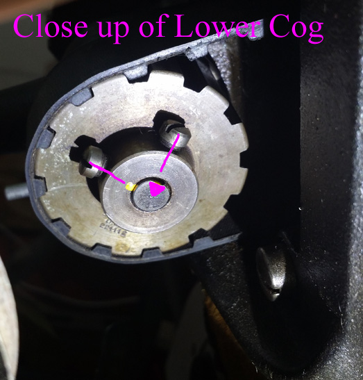
Tejas - thanks for the manual it is going to help. Uwe - thank you for taking the time to make the video. Eric - thank you for your time too. Uwe, my collar part #2040060 is the same as yours, marked with an "S" closest to the set screw that goes into the V-groove on the shaft. My lower cog part #224112 does not look like yours. I wonder if my machine serial W1790118 is a 1950's version or the 1911-1919 version, if that matters? Early or late, our cogs are totally different. My "S" stamp is adjacent to the opposite screw (see pic). That is important... 2 different parts, with 2 different set screw alignments, used in the same location. That could mess some people up. So I have a choice. I can go with aligning my screws to look like yours in the video... V-groove screw on top and shaft screw to the right. --- or --- Use the "S" stamp to note what screw goes in the V-groove... V-groove screw on top and shaft screw to the left. Given my machines troublesome past, and my timing arrows line up perfect when I use the "S" stamp method to determine the cogs position, logic dictates I go with that. I'm hoping I will see more of these "S" stamps as I progress through this rehab. BTW, where is the best orderly list of steps to guide me? Thank guys, Will in Central Florida
-
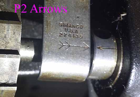
Thanks Eric and Uwe. Hehe - I think my lower belt cog was out 90*. This morning I determined the top shaft belt cog can only sit in one position, as you know, because it is pinned. The bottom cog with 2 set screws can sit in 2 positions. I tried both. With the take up lever at TDC, my old cog position (P1) had my arrows misaligned 1/8". Rotating the cog 90* counterclockwise into position two (P2) my arrows are dead on. As far as the set screw marks on the shaft - there were marks for P1, and maybe slight marks for P2. but honestly hard to tell. Can somebody verify one set screw goes in the "V" grove and the other is to the left of the groove (see picture)? Eric you were right about the 2 styles of set screws, flat and pointed. And mine where in the wrong holes relative to the "V" groove... but not if I rotate the cog 90* into P2. My feed dog connecting rod is half way between "bottom" and "out", but if that is not a clue to an issue then I'm good with that. Thank you, Will from Central Florida
-
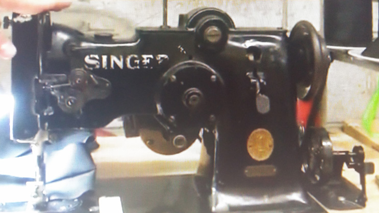
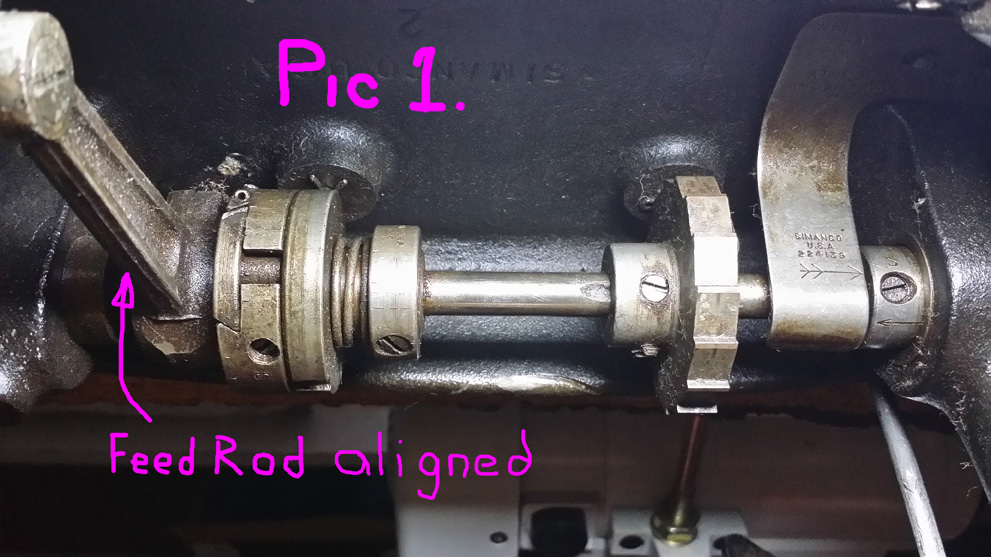
Hi Guys and Dolls. My first post after lurking for 3 months. I love this forum, one of the best I have ever been on. So I have been making a small product from garment leather and was sewing it (or struggling to) with a Singer household machine. I located and purchased a Singer 111W155 with table and new Consew Servo motor for $175. The previous owner was fed up taking the machine in for repair. Right now it won't sew. Leather or fabric won't move etc. It looks like a new timing belt has been installed so I thought I would check the upper and lower main shafts timing. According to this video https://www.youtube.com/watch?v=5ZXu--P2ips to have the upper and lower shafts in time, the Feed Drive Connector Rod should be at its lowest point of arc and perpendicular to the lower main shaft (see picture 1) and the thread pickup arm is at its highest point and the 2 arrows should be aligned. My arrows are not aligned and my thread take up arm drops 3/8". When I put the arrows together and have the thread take up arm at its highest position my Feed Rod is not in the correct position ( see picture 2) according to the video. What is out of whack or is it supposed to be this way? Thank you, Will Central Florida


