
ThomasA
-
Posts
8 -
Joined
-
Last visited
Content Type
Profiles
Forums
Events
Blogs
Gallery
Store
Everything posted by ThomasA
-

Backlash issue with Juki 1541 & bonded thread
ThomasA replied to aslfkjaslfkjasflkj's topic in Leather Sewing Machines
@aslfkjaslfkjasflkj, just out of curiosity, did you ever solve this issue? I just had the exact same problem with uneven bobbin tension after adding an anti-backlash spring. It turns out that I have three models of bobbins. One, the old original, didn't spin at all. Three black was smooth as butter. 20 shiny ones from China jerked terribly. The original bobbin was too thick for the spring, but it worked fine without it. The spring is 0.5 mm. The other bobbins clear the spring OK, so that's not the problem. But it turns out, the 20 stainless ones is 0.15 mm larger in diameter and the center hole is 0.08 mm larger than the black ones and the original. It's enough for the bobbin to start rubbing and semi-bind to the bobbin case wall. The bobbin MUST only ride on the center post in the bobbin case. I reduced the diameter of a bobbin to verify my finding and yes, that was the problem. -
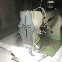
Ah, thank you Glenn! OK, so it's supposed to get squeezed into the slot where the block rides? Or how can it "sit" on top of it? It seems like I will have to remove the rockframe to replace the felt. I haven't done that yet. Maybe it will be obvious when I see it from the other side. thomas
-
OK no answer, but I found this post!
-
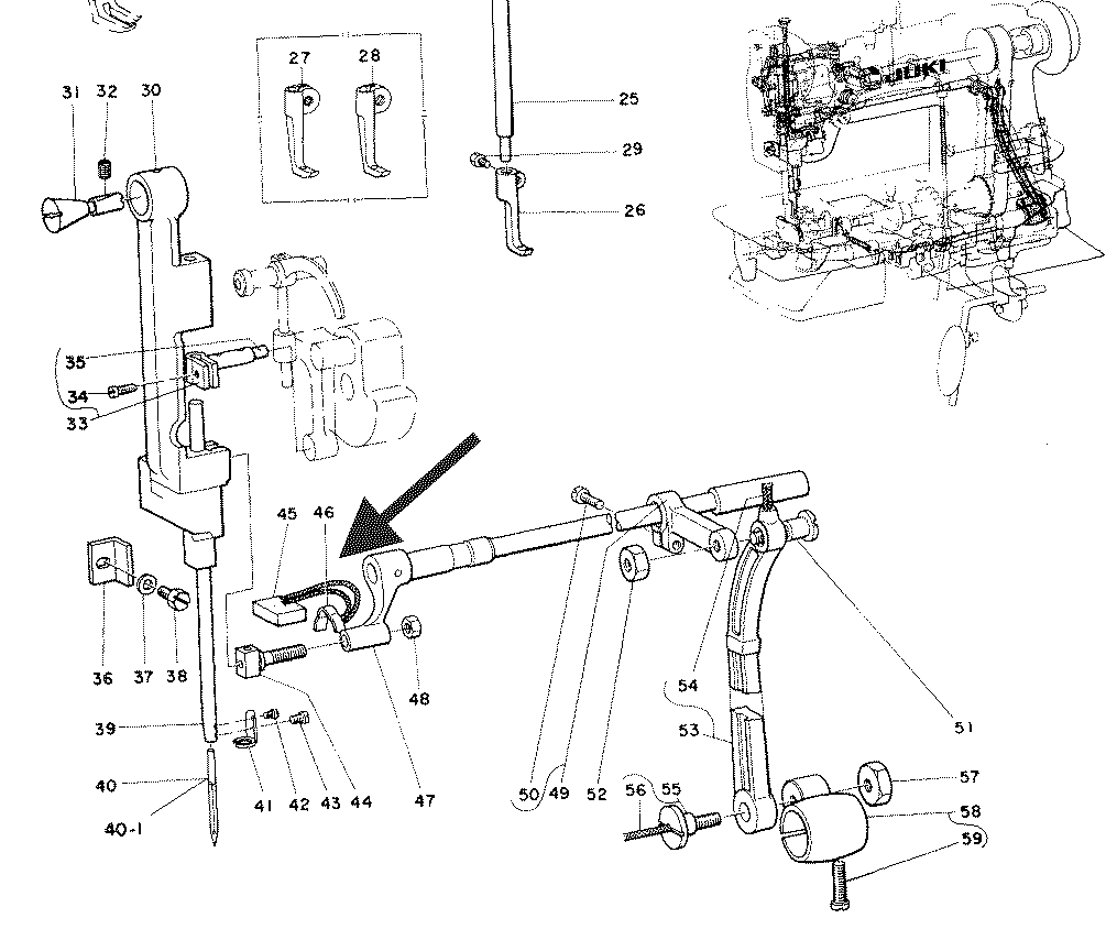
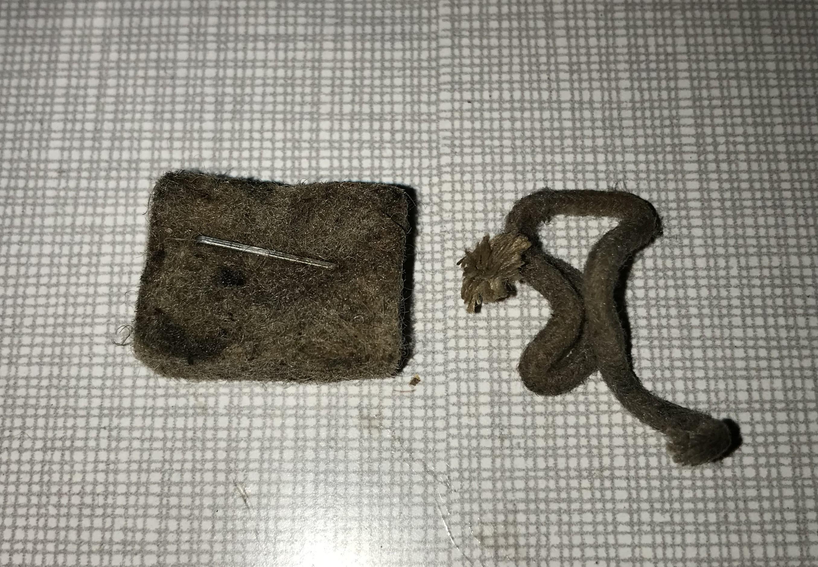
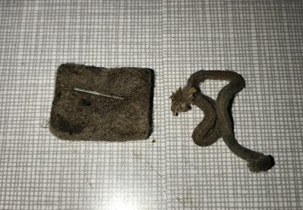
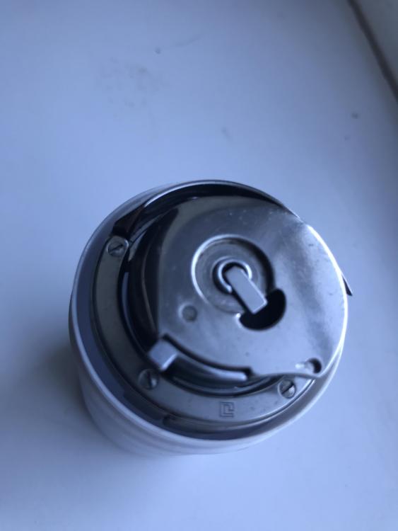
Hi all, I got this felt pad and a loose oil wick with the machine. I haven't thought about it, but then I stumbled across this parts listing that has a match. However, I cannot find a good place on the rock frame assembly where it seems to fit. Someone who knows how is mounted?

-
Screws and Bolts for 111 Walking Foot / Feet
ThomasA replied to suzelle's topic in Leather Sewing Machines
I realize this is an old topic but since I’m also on the hunt for something better than slotted heads I would like to fill in what I found out so far. The screws for the Singer 111w feeding system are: Presser foot: 9/64” 40 tpi L: 9 mm (.350”) (.200 part threaded). Alternative: #6-40 L: 9.5 mm (.375”) Drive: T-10 / 7/64 hex. Full threaded. (?) Walking foot: 11/64” 40 tpi L: 6.5 mm (#9 …) Throat plate: 11/64” 40 tpi L: 8.5 mm countersunk head. (#9 …) Feed dog: 1/8” 40 tpi L: 6.35 mm (.250”). Alternative: #5-40 UNC hex head - head may be slightly high and rub the throat plate) Needle screw: 1/8” 44 tpi L: 4.5 mm (.180”)(or 3.8 mm (.150”)). Alternative: #5-44 UNF -
OK, nice to have .134” confirmed! My old hook kit, with that finger width, came in my Lu-563 but is probably a B1830-521-0A0 with encased bobbin. That type normally comes in double needle machines like LUH-521 and LU-1565. Fits well in a 563, but it’s a bit tedious to change the bobbin. Don’t know what the pros are? Anyway, I will now make the B1830-563-BA0 finger have the same width.
-
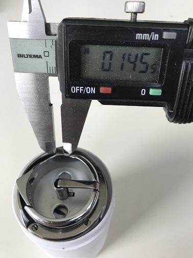
Tanks Glenn! Could you perhaps give me a sample of bobbin case finger widths? I have one that is 3.40 mm (.134") and another one that is tapering, but 3.70 mm (.146") where it meets the throat plate grove. I'm hesitating to grind it down to match the narrower one... Because its expensive, and even though the narrower one works I would rather know what I'm doing and aim for standard dimensions...
-
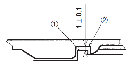
Interesting, I have questions on the same topic. I realize hook assemblies differ in the details, but are they offered in three width versions? Width of the locating tab? Or the height of it? Anyway, I looked at Collages web shop but could not find it. In this context I'm looking at the hook locating grove on the throat plate. Both height and width of the grove varies a lot between the throat plates I have. The clearance provided in height with six different throat plates (combined with one of the hooks) varies between 0.83 and 1.38 mm. That's more than the tolerance for one adjustment of the hook height, but if you measure the width of the grove, it varies even more - 0.52 to 1,70 mm. The thread is supposed to pass here so if 1 mm is needed on the top, 2 millimeters would be logical on the sides as the thread passes on both sides of the tab simultaneously - but that does not seem to be the case as most throat plates I have has a measurement on the lower side - less than one mm total clearance measured on one side of the tab. This is obviously dependent of the width of the locating tab of the hook assembly ut it is measured with the B1830-563-BA0 assembly for "extremely" thick thread - it should give clearance for that one could think. (It's tab is 3,70 mm wide half way out on the tab - where it meets the grove.) So my question is, when I go down to the machine shop to finish my attachments, what dimensions should I aim for? Is there a downside to having too much clearance? One manual says something like "The hook should be high enough to stop the rotation and low enough to pass the thread". That's up and down (no measurement needed), but nothing about sideways. I've looked for specifications or drawings of this stuff, but it seems to be rare. Can anyone fill in some of the blanks?