Search the Community
Showing results for tags 'speed reduction'.
-
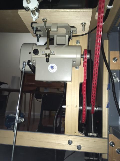
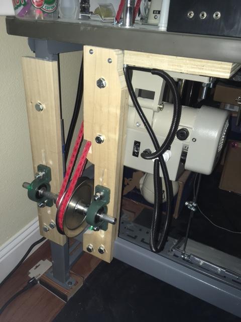
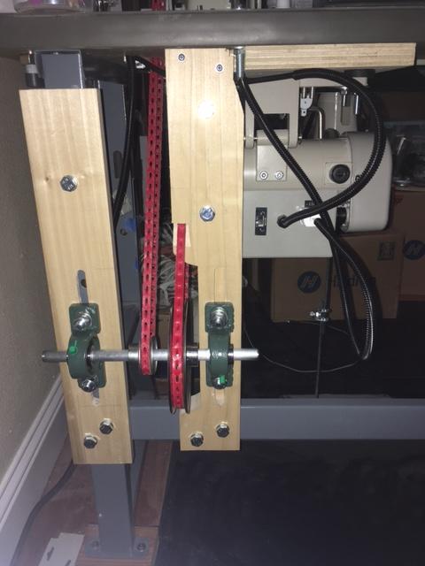
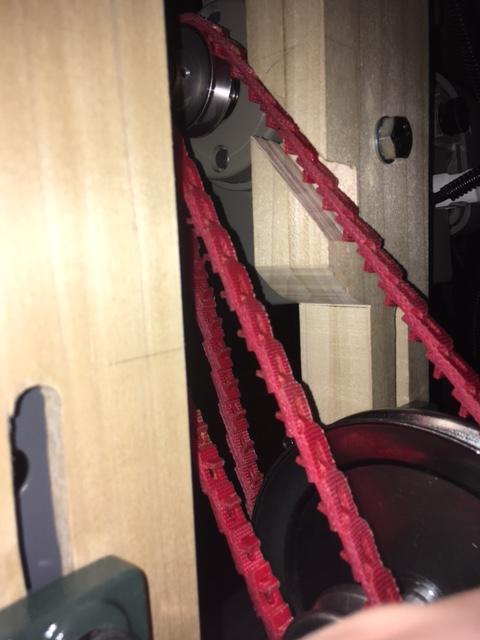
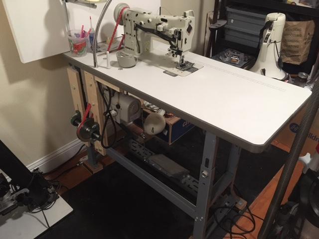
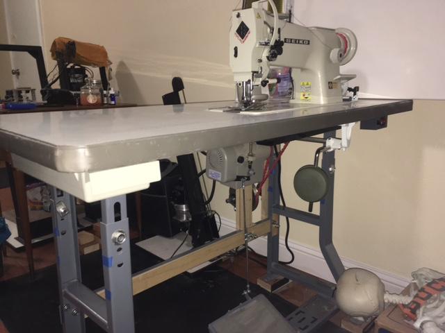
Back in 2018, I got hold of a STH-8BLD-3. I used it for a couple of small leather projects, but without a speed reducer, it primarily it saw use for heavy canvas on a theatre gig I was doing at the time. In 2019 I moved across the country and my art/craft/hobby area had to be colocated with the cats' litter boxes for the past few years. I've had plenty of other stuff to do in the meantime, so I've kept my machines bagged until the last of the kitties eventually passed on. Now that I'm able to eradicate the clouds of fine dust from the room, I've started setting things up again. Regarding speed reduction, I researched the topic on the forums back in 2018, and again recently. After considering others' builds as well as the purpose-made products available, I still chose to go the DIY route. The factors leading to my DIY decision: I felt that I could build a reducer for less than the cost of a commercial product. As it turns out, I can--so long as I'm paying myself in beer. I really really really didn't want to cut or drill extra holes in my table. This was really the biggest factor. Every other solution I'd seen required modifying the existing belt hole or was a new top build. I hate myself apparently and don't have enough problems There are likely simpler ways of accomplishing this, but here's what I cobbled together with a band-saw, drill-press, dremel and hand tools. Maintaining the original angle coming down from the hand-wheel prevented the need to modify the slot, but made for a long stretch. I haven't measured each belt, but the two add up to ~9ft. This worked to apply load to the pillow-blocks in their strongest direction, directly into a leg; though, beefy as they are, I doubt it much matters here. Note, the belt going to the machine head is on in the wrong direction in these photos. The vertical boards, and the horizontal bit inside the cross-brace (pictured further below) are all 1x4" poplar. The slots for the bearing mounts were done on the drill press by setting a fence to slide the board along while drilling a LOT of holes with spade & Forstner bits, then cleaned up with a chisel. The bolt heads and spring washers sit in a pocket and can slide up or down. For the motor mount, I plotted out the base on graph paper and made a template to shift it left and back enough to be out of the initial belt line and to not interfere with the original bolt locations. This ended up being a really tight fit for belt adjustment at the end; if I did it again, I'd position the motor a quarter to half an inch forward. This worked out because link belt is forgiving, and I designed this to allow for adjustment at the pulleys in addition to the motor. It's two pieces of 1/2" birch ply, with the motor bolt heads countersunk and hidden between the boards & table. These bearings are adjustable, however, the ones I received were very stiff initially. Even after greasing, I worried I'd break something while trying to get them aligned. I ended up bolting each pillow-block to a 2x4 clamped to my bench and worked them around for a while with a 3ft rod until they loosened up. For the axle, I cut steel bar down to size & chamfered the ends. Using a dremel and file, between bouts of sciatica, I ground about the ugliest usable flats that I'll never show you for the pulley & bearing set-screws. Because my flats are dodgy, and because both pulleys have key-ways & I'm not using keys, I balled up lengths of electrical solder to fit comfortably in each set-screw hole, which mushed down and engaged nicely. This also prevented the set screws from extending into the empty key-ways where they'd be unsupported & weakest. Once I got everything tensioned, it all moved nicely by hand and easily penetrated several layers of heavy canvas. I'll get some leather under it later this week and see how it does. I suspect I may want to move up to an 8" pulley and designed with this in mind, however I may look to a larger handwheel first if I still find it too fast.
- 9 replies
-
- speed reduction
- sth-8bld-3
-
(and 1 more)
Tagged with:
-
Does anyone have any suggestions for slowing down a Consew machine. I have reduced the size of the drive pulley as small as is possible. when sewing, the machine seems to lack torque to start, so you require lots of pedal, but then the piece takes off. Once you're sewing it is easy to throttle the machine back to a creep with delicate manipulation of the foot pedal. does anyone make a larger handwheel for these machines. I know sailrite makes one for their machine. It occurred to me to machine a 2 part pulley/disc/donutish sorta thing that could be bolted onto the existing handwheel, but I don't want to reinvent...the wheel!!!! Thanks, brent
- 2 replies
-
- clutch
- consew 206
-
(and 1 more)
Tagged with:
-
Not trying to beat a dead horse here but many of you folks have seen and commented on this video from you tube https://www.youtube.com/watch?v=9y2Aapk7X8E&t=3s . The author makes claims and shows proof of concept for changing the pulley on the servo motor to a 50mm smaller one and instead of a standard speed reducer, he proposes changing the hand pull on the actual head to a larger one. He is using a consew 205RB-5 machine and after he changes out the pulleys, it does show a significant change in slowing down the system in a similar way that the generally accept method achieves. I recently purchased this machine and saw the video and it has been on my mind ever since. I have changed out the hand pull for a 6" one and will be changing the servo one later tonight before adding the correct belt. He makes the claim that no one is talking about this. He sort of infers that that is because all of the people he has spoken to that are in the business do not want to lose business if everyone starts doing this. Some of you have mentioned that the cost of the larger pulley for the head has gained because of the video and I myself have verified that the costs are certainly higher than is quoted in the video. I have also spoken to two people in the business representing consew and also an industrial sewing machine company doing business for 50+ years and both of them said " the machine was not designed to use a larger and heavier hand pull. Why don't you just do it the way that is widely used, proven, and readily available? " but they were either unwilling or unable to provide what I would deem a logical and acceptable explanation as to just HOW it would damage the machine. I personally am not a technician. I have spent maybe 5 solid hours watching "consew 206rb-5 maintenance video #1, and #2 while I had my thinking cap on and tools in hand under the proverbial "hood" of my machine. This qualifies me to be classified as a "caveman holding a rock but still having to wait for lightning before I get to use fire" compared to some of you cherished lifers. I can make no claims based on knowledge, experience, and understanding. that is why I am offering this subject up to public forum hoping some real technicians will respond and we all will learn and grow. inside the machine there are several places that are two moving parts each with a mark someone has made that should line up when the needle is in a certain a deliberate position. is it possible that a larger wheel mean less or more revolutions so these marks will no longer line up. ergo a timing or maintenance issue reason for not using a larger pulley? obviously showing my lack of experience not knowing if that would cause more or less RPM, but im trying to understand why??? Thank you all for your time and help. I need it.
-
Hi Sewers, thanks for your interest - this is how I slowed-down and torqued-up my 120-2 with a cameo by my 105-27. I turned the huge hand wheel around to get it's v-belt groove closer to the machine so that the motor wouldn't have to be cantilevered too far. The first photo also shows the new bobbin-winder drive wheel which was in my pile for 20 years. I have no idea why I have it or what it's from. There's no reason to think it's for a sewing machine but it has just the right offset and is much nicer than the original plastic-hubbed Adler part. The second photo shows how tight the fit is. The swing arm is 1/4"x 1-1/2" stainless steel. I like to mount the intermediate pulleys on a swing arm so that the belts' lengths are not critical. The third photo shows the pulleys I turned out of aluminum, the smaller one is press-fit into the larger and has two bearings pressed-in; one each side. I try to use skate bearings whenever possible because they are common and inexpensive. If they can handle a 200lb knucklehead hucking massive air, they are up to this job. That's engineering. As I mentioned, it's my policy to not make any irreversible changes to a machine, so the positions of existing holes somewhat dictate the design. The big pulley has a hole in it for the hex key to tighten the swing arm pivot bolt. On the 105, I pressed-in a sintered bronze bushing for the pivot shoulder bolt but that was unnecessary for a pivot that's rated for 0 RPE (Revolutions Per Ever) The 120 has its big plinth with holes in opportune positions for the aluminum angle bracket on which I mounted the motor, controller and box of electronics. I milled vertical slots in the bracket to allow tensioning of the v-belts but one weakness of this design is that I have to remove the electronics box to loosen/tighten the motor bracket bolts. The controller is mounted diagonally so that the arm doesn't stick to far out the back and it doesn't intrude on the clearance between the spine of the machine and the needle. They are much more expensive than a regular rubber belt, but the twist-lock style belts allow me to vary the design as I go without a hundred trips to buy wrong-length belts. I like the twist-lock belts but they aren't too happy with small pulleys because they offer less contact area than solid rubber belts. I wipe contact cement or gasket dressing onto the contact surfaces, letting it dry before installing the belt, to make them a little stickier. But that's just me, Gary
- 5 replies
-
- was not leather
- adler 120
-
(and 2 more)
Tagged with:


