esantoro Posted November 22, 2008 Report Posted November 22, 2008 I've got two 22-watt circline fluorescent magnifying task lamps. They are very well made but for the electronic ballast, which has burnt out in both. Instead of throwing the lamps out, I decided to try to buy two magnetic ballasts and use them to replace the burnt out electronic ballasts. (Are "ballast" and "transformer" synonymous terms?). I Ordered magnetic ballasts but was sent two plug-in ballasts. Before I send them back, I was thinking that these plug-in ballasts/transformers (which have a magnetic ballast built-in) may work out even better and they were the same price as the magnetic ballasts, anyway. These plug-in ballasts/transformers have two shielded wires coming out and are stripped of 1/4" insulation on the end. Only one of the wires has specs printed on it. I'll post pictures a bit later for clarification. First Question: How do I tell which of the two wires coming out from the ballast/transformer/adapter/wall plug/wall wart is positive and which is negative? Second question: Once I figure out which is positive and which is negative, which one should go directly to the 4-hole plug that fits the four prongs of a 22 watt circline fluorescent bulb, and which should go directly to the on/off switch on the lamp? If the specs that are printed on one of the wires is any indicator of polarity, as long as everything else was constructed to standards, the original lamp wiring has the printed wire going directly to the on/off switch. I know pictures would be much more helpful, and I will post them later. Thanks for the help, Ed Quote http://www.waldenbags.com http://www.waldenbags.etsy.com
Contributing Member TwinOaks Posted November 23, 2008 Contributing Member Report Posted November 23, 2008 (edited) As it happens, I'm an electrician who's currently working for a lighting service company as a lighting technician. You've posted this in exactly the right place!!! When you post the pics of the ballasts, please include the wiring diagram which is usually on one side of the ballast, or occasionally on an included sheet of paper. Armed with those, I should be able to guide you through the replacement. If it is what I'm thinking, you may also need to purchase a starter for it. It really depends on the fixture. Please note that the type of lamp you use is determined by the type of ballast, or if the lamp is good, the lamp determines the type of replacement ballast. I find it odd that you've opted to use magnetic ballasts over electronic. A lot of what I do is retrofit electronic ballasts to fixtures containing magnetic. Years ago, magnetic was the best available and they were built differently (read as BETTER). I've changed out magnetics that are date stamped as early as 1964. The newer magnetic ballasts only have a warranty of 24 months, and some not even that long. 'Ballast' and 'transformer' are NOT synonomous in a technical sense, but are often used to talk about the same thing. In your case, it isn't possible to distinguish between the two, as it is a one piece unit. In other systems, like pole lights, the components are more modular. A ballast will contain a transformer, a capacitor, and depending on the application, an ignitor or starter. In your type of application, everything will be sealed in a neat little box. Edited November 23, 2008 by TwinOaks Quote Mike DeLoach Esse Quam Videri (Be rather than Seem) "Don't learn the tricks of the trade.....Learn the trade." "Teach what you know......Learn what you don't." LEATHER ARTISAN'S DIGITAL GUILD on Facebook.
esantoro Posted November 23, 2008 Author Report Posted November 23, 2008 As it happens, I'm an electrician who's currently working for a lighting service company as a lighting technician. You've posted this in exactly the right place!!!When you post the pics of the ballasts, please include the wiring diagram which is usually on one side of the ballast, or occasionally on an included sheet of paper. Armed with those, I should be able to guide you through the replacement. If it is what I'm thinking, you may also need to purchase a starter for it. It really depends on the fixture. Please note that the type of lamp you use is determined by the type of ballast, or if the lamp is good, the lamp determines the type of replacement ballast. I find it odd that you've opted to use magnetic ballasts over electronic. A lot of what I do is retrofit electronic ballasts to fixtures containing magnetic. Years ago, magnetic was the best available and they were built differently (read as BETTER). I've changed out magnetics that are date stamped as early as 1964. The newer magnetic ballasts only have a warranty of 24 months, and some not even that long. 'Ballast' and 'transformer' are NOT synonomous in a technical sense, but are often used to talk about the same thing. In your case, it isn't possible to distinguish between the two, as it is a one piece unit. In other systems, like pole lights, the components are more modular. A ballast will contain a transformer, a capacitor, and depending on the application, an ignitor or starter. In your type of application, everything will be sealed in a neat little box. Mike, Your response makes me feel so good. I don't have my pictures yet, but I have attached PDF instructions from a guy who has made a similar repair with the exact same lamp. His instructions gave me the confidence to save these lamps until the day I worked up the nerve to attempt fixing them. Because I was unable to find the circline adapter with a magnetic ballast, as instructed in the PDF, I attempted to order a magnetic ballast fro California. The did not send me a magnetic ballast like the one in the PDF. Instead they sent me a wall wart/plug-in ballast with two wires coming out. I'm thinking that this wall wart might be a better route. I do know that the wall-wart/transformer/plug-in ballast is indeed rated for a 22-watt circline fluorescent bulb. It is actually intended for the LM747 handheld lamp listed on this page: http://www.affordaproducts.com/visualmate.htm The magnetic ballast that I had attempted to order is the BL022 listed on the following page. I received, however, the "22-watt ballast" listed on the same page: http://www.affordaproducts.com/accessories.htm Thank you ever so much, Ed LampFix.pdf LampFix.pdf Quote http://www.waldenbags.com http://www.waldenbags.etsy.com
Contributing Member TwinOaks Posted November 23, 2008 Contributing Member Report Posted November 23, 2008 Ed, you sure find some interesting problems to adopt. I'll start off by saying "use only manufacturer recommended replacement parts", to C.M.A. If the plug they sent you has exposed ends/wires, it probably attaches at the starter plug. If instead, it has a pin and ring plug, I'm not so sure without having "eyes on". If you're intent on using the magnetic replacements, I suggest checking around for an electrical supply house, or possibly a lighting center to check for the BL022. It's an inline ballast. Connect the line side (hot from the wall) to one of the ballast wires, and the other ballast wire to the starter, and from starter to one end of the lamp. Other end of the lamp returns to ground.(the neutral wire).Staying with what they sent: Keep in mind that most two wire cords like that have ribs/ridges on one side of the cord. That's your 'hot'. I advise staying away from the .pdf modification. There are several things "wrong" with it, primarily, placing a core and coil transformer in the base without any mounting points. Those transformers generate a fair amount of heat, and are made the way they are so that they can radiate some of that heat away. Wrapping with electrical tape is a bad idea. Likewise, wrapping the connections with electrical tape is a band aid at best. It's better to choose a connector type that doesn't leave exposed conductors which complies with the NEC 410.5, no live parts shall be exposed. NEC410.130 (G), [2,3] basically says "you've gotta have a way to cut power at the fixture" so we use a little connector made by Ideal- part no. 30-102. It's safe and leaves NO exposed wires. Even if you decide to use spade clip connectors, choose the type that is completely enclosed in insulation, or use a butt connector and put heat shrink over it. I also have to ask what the cost of all this is going to be. Most items these days are more or less "disposable", and are built for replacement rather than repair. If the fixture was built with a small physical size electronic ballast, the magnetic one may not fit in the fixture. At that point, you've got a magnifying glass on an arm. It might be better to update the lighting in your whole work area. In anycase, proceed with caution, and make sure your power is disconnected. I'll try to answer further questions as I can. This type of de-retrofitting can get a little screwy at times. Personally, I'd look for a 6 foot long LED rope light and coil it inside the round reflector, gut the wiring, and replace it with the power supply for the LED. Quote Mike DeLoach Esse Quam Videri (Be rather than Seem) "Don't learn the tricks of the trade.....Learn the trade." "Teach what you know......Learn what you don't." LEATHER ARTISAN'S DIGITAL GUILD on Facebook.
esantoro Posted November 23, 2008 Author Report Posted November 23, 2008 Ed, you sure find some interesting problems to adopt. I'll start off by saying "use only manufacturer recommended replacement parts", to C.M.A.If the plug they sent you has exposed ends/wires, it probably attaches at the starter plug. If instead, it has a pin and ring plug, I'm not so sure without having "eyes on". If you're intent on using the magnetic replacements, I suggest checking around for an electrical supply house, or possibly a lighting center to check for the BL022. It's an inline ballast. Connect the line side (hot from the wall) to one of the ballast wires, and the other ballast wire to the starter, and from starter to one end of the lamp. Other end of the lamp returns to ground.(the neutral wire).Staying with what they sent: Keep in mind that most two wire cords like that have ribs/ridges on one side of the cord. That's your 'hot'. I advise staying away from the .pdf modification. There are several things "wrong" with it, primarily, placing a core and coil transformer in the base without any mounting points. Those transformers generate a fair amount of heat, and are made the way they are so that they can radiate some of that heat away. Wrapping with electrical tape is a bad idea. Likewise, wrapping the connections with electrical tape is a band aid at best. It's better to choose a connector type that doesn't leave exposed conductors which complies with the NEC 410.5, no live parts shall be exposed. NEC410.130 (G), [2,3] basically says "you've gotta have a way to cut power at the fixture" so we use a little connector made by Ideal- part no. 30-102. It's safe and leaves NO exposed wires. Even if you decide to use spade clip connectors, choose the type that is completely enclosed in insulation, or use a butt connector and put heat shrink over it. I also have to ask what the cost of all this is going to be. Most items these days are more or less "disposable", and are built for replacement rather than repair. If the fixture was built with a small physical size electronic ballast, the magnetic one may not fit in the fixture. At that point, you've got a magnifying glass on an arm. It might be better to update the lighting in your whole work area. In anycase, proceed with caution, and make sure your power is disconnected. I'll try to answer further questions as I can. This type of de-retrofitting can get a little screwy at times. Personally, I'd look for a 6 foot long LED rope light and coil it inside the round reflector, gut the wiring, and replace it with the power supply for the LED. Mike, I just get an idea and can't put it down. In the long run, I acquire quite a bit of knowledge about a lot of things. That eclectic knowledge ends up coming in handy for disparate things further down the road. I've got firends who spend hour playing poker every week. Fiddling with things is my poker. I approach as if it's a game. I like these magnifying lamps, and they are well made. I bought them each for about $25 on Ebay. To replace them now would cost $120 to $160. These plug-in ballasts were $15. Everything but that electronic ballast is very well made and I hate to throw stuff away if I have a suspicion that a fix wouldn't be too difficult and just a matter of assembling the right bit of information. I see people throw out laptops. I pick them up and remove their usable internal parts: hard drive, memory, optical drives, etc. I also hate the mentality with which corporations have brainwashed us into thinking that we need to replace their preplanned malfunction. Thanks for the bit on the ribbed wire. Of the wires coming out of the ballast/transformer, one has printed specs on it and the other is ribbed. I looked closer at the lamp wiring. IT has three wires coming from the three-pronged plug: green (ground), black, and white. Those wires go into the base of the lamp. Inside the base of the lamp, the green wire is connected to a metal plate. The black wire is connected to a printed wire that runs through the arm up to the circline bulb. That wire connects directly to the on/off switch. The white wire going into the base connects to the ribbed wire, which runs through the arm, up to the circline bulb and connects directly to the burnt-out electronic ballast. My educated-guess fix is to remove the original wires going into the base and substitute them for the wires coming of the new plug-in ballast, which is rated for a 22-watt circline fluorescent bulb, the same that my lamp requires. Inside the base of the machine i would substitute the ribbed wire off the plug-in ballast for the original white wire, and the other wire off the plug-in ballast for the black wire. The only thing missing would be the ground wire, which may be obviated by the plug-in ballast. One thing for which I'm not very sure is what to do about a starter plug. If it's possible that the plug-in ballast contains a starter plug, then I'm fine. This is what I'm hoping for. However, even if that is the case, I would still need to know how to connect the female plug that connects to the four prongs of the circline bulb to the two wires coming through the arm of the lamp: one goes directly to the on/off switch, the other is the ribbed wire. The PDF directions show a start-plug that was taken from an adapter with a magnetic ballast (copper wire wrapped around iron). This start-plug has only two wires coming off it. I'd like to use the original female plug on my lamp, which has four wires coming off it: two sets of black and white. Is it possible just to treat each set as one wire or must they cross: the white from one and the white from the other being treated as one wire; and then the same for the black. I have attached a picture of these wires. Thanks, Ed Quote http://www.waldenbags.com http://www.waldenbags.etsy.com
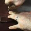
Contributing Member TwinOaks Posted November 23, 2008 Contributing Member Report Posted November 23, 2008 (edited) Okay, Now I see what you're dealing with....I guess the pic is worth quite a few words, huh? Provided the cord from the plug in units you have are delivering the output voltage of the ballast (this seems to be the case) then you are correct- tie the four leads from the lamp plug to the new cord as you propose. The three wire cord that is previously the power supply is as follows: black wire is the hot, white wire is the ground (commonly called neutral), and the green wire is the grounding wire. Green wire's job is to ground the fixture, supply an alternate path to ground for the voltage, if the normal path to ground is interupted. Basically, it's there to keep you from getting the stuffing knocked out of you when a wire burns out and contacts the metal of the fixture. From your last post, you mention the ribbed wire connects to the white (power supply cable) wire. I think you may have the reason why it burned out- it sounds like the ballast was wired backwards. As I read it, the plug/cord unit you have is an enclosed unit and the cord is the output from a ballast. If you have the tools to do so, use a volt meter to check continuity between the circuit and the fixture body to ensure it isn't shorting out, before plugging it in (should be no continuity, and (0)zero means theres no resistance which = dead short), and the output from the ballast you have- at the end of the cord, of course. As long as the fixture isn't shorted to the circuit, and all presumptions about the cord from the transformer body are correct, you should be fine. Please be careful with this project, and if you are unsure about something, consult a local electrician. I give this advice in an attempt to help you out, but I obviously can't pick it up and test it myself, so I might be missing something. I'm a little bit uncomfortable with giving the advice, and I won't be insulted at all if you need to take it to someone for a hands on look at it. Good luck with the repairs. Edited November 23, 2008 by TwinOaks Quote Mike DeLoach Esse Quam Videri (Be rather than Seem) "Don't learn the tricks of the trade.....Learn the trade." "Teach what you know......Learn what you don't." LEATHER ARTISAN'S DIGITAL GUILD on Facebook.
esantoro Posted November 23, 2008 Author Report Posted November 23, 2008 Okay, Now I see what you're dealing with....I guess the pic is worth quite a few words, huh?Provided the cord from the plug in units you have are delivering the output voltage of the ballast (this seems to be the case) then you are correct- tie the four leads from the lamp plug to the new cord as you propose. The three wire cord that is previously the power supply is as follows: black wire is the hot, white wire is the ground (commonly called neutral), and the green wire is the grounding wire. Green wire's job is to ground the fixture, supply an alternate path to ground for the voltage, if the normal path to ground is interupted. Basically, it's there to keep you from getting the stuffing knocked out of you when a wire burns out and contacts the metal of the fixture. From your last post, you mention the ribbed wire connects to the white (power supply cable) wire. I think you may have the reason why it burned out- it sounds like the ballast was wired backwards. As I read it, the plug/cord unit you have is an enclosed unit and the cord is the output from a ballast. If you have the tools to do so, use a volt meter to check continuity between the circuit and the fixture body to ensure it isn't shorting out, before plugging it in (should be no continuity, and (0)zero means theres no resistance which = dead short), and the output from the ballast you have- at the end of the cord, of course. As long as the fixture isn't shorted to the circuit, and all presumptions about the cord from the transformer body are correct, you should be fine. Please be careful with this project, and if you are unsure about something, consult a local electrician. I give this advice in an attempt to help you out, but I obviously can't pick it up and test it myself, so I might be missing something. I'm a little bit uncomfortable with giving the advice, and I won't be insulted at all if you need to take it to someone for a hands on look at it. Good luck with the repairs. I'm not taking it to anyone else. This is 90 percent of the fun. I'm almost there. I've uploaded more pictures. Who knows, maybe this information will come in handy as a bunch of these lamps may end up being available very cheaply in the future. All it comes down to is how I connect the two wires from the plug-in ballast, which I now feel is indeed a better route than just the magnetic ballast from either my California source or a difficult-to-near-impossible-to-find adapter with the magnetic adapter. Basically, should the ribbed wire go directly to the female plug for the bulb,and the other wire directly to the on/off switch? In the original setup, just in case I haven't already detailed this, the white wire from the power source is connected to the ribbed wire that runs through the arm and connects directly to the female plug that connects to the bulb. This might indeed be why the electronic ballast burnt out after two months of use. That's fun to diagnose the problem. Everything is telling me that the plug-in ballast, which was designed for a handheld 22-watt circline magnifying task lamp, does include the starter plug. By the way, what's the damage risk if I wire up this thing and no starter plug is indeed installed? Will the lamp simply not start, or will something more serious happen? About the four wires from the female plug to the burnt out electronic ballast. To be clear, these four wires have to connect directly to the two wires coming from the plug-in ballast. I'm not certain how these should be connected. Here are my options (additional pictures have been uploaded): 1. connect them any way, as all that is important is that current flows through the female plug. I wouldn't imagine this to be the case. 2. Attach the black and white from one side of the female plug to the ribbed wire (hot wire, which I will correlate with the ribbed wire coming from the plug-in ballast. And attach the black and white from the other side of the female plug to the wire that goes directly to the on/off switch. 3. Attach the two black wires from the female plug to the ribbed wire coming from the plug-in ballast. and Attach the two white wires to the wire that goes directly to the on/off switch. I've attached additional pictures. Thanks Ed Quote http://www.waldenbags.com http://www.waldenbags.etsy.com
Contributing Member TwinOaks Posted November 24, 2008 Contributing Member Report Posted November 24, 2008 Thanks for the additional pics, it helps to clarify what we're discussing. Now I can really see the new ballast. At this point, since you've eliminated the circuit board, all the female plug wires do is connect the new ballast to the lamp. Look at the female plug- you'll see that both black wires are on the same side, but on the circuit board they go to separate terminals from the white ones, y1 (blk), w1 (wht); and presumably y2, w2. Just look at the circline lamp and be sure that the black wires both go to one 'side' of the lamp. This will be easy, as the plug should be keyed. If they both go to the same side, which it appears to do on the presumption that the pic of the female plug is oriented the way it plugs into the lamp, hook the black wires together and to one of the ballast leads. Repeat with white wires. I suppose to be "correct" it should be the ribbed side of the cord, but it won't really matter. All the electronic circuit routing is carried out INSIDE the little black box, and the ends you have to work with are just the ballast output. The power goes in one side of the lamp, and out the other. It probably isn't even neccessary to have both leads (of a pair) connected. If you try it with only 1 black, 1 white and the end of the lamp just glows, it needs both. On retrofits, where mag. ballasts are replaced with electronic ballasts, it's typical to have two wires to the socket (each side of a bi-pin lamp end) and we just run the single lead for that lamp to it and tie all three together. That makes the other end of the lamp the return side and they all share a common lead. If by chance, the black wires are split to each end of the lamp, just pair them up as on the circuit board. To use the switch, simply put it in series with one side of the circuit. Be aware that if you break the neutral side, you'll still have the ballast output running to the lamp which may prematurely burn out the cathode inside the lamp. I think a better option in this case is to have the new ballasts plugged into a power strip with the switch in that, because the ballast output isn't usually switched. It's almost always on the power supply to the ballast. Plus, the new ballasts don't have a switch installed so it probably is intended to be just unplugged when not in use. Another benefit is that if everything goes completely wrong, you'll kill the fuse in the strip instead of tripping the breaker in the house, causing a temporary blackout at the precise moment something critical happens on "Heroes". Quote Mike DeLoach Esse Quam Videri (Be rather than Seem) "Don't learn the tricks of the trade.....Learn the trade." "Teach what you know......Learn what you don't." LEATHER ARTISAN'S DIGITAL GUILD on Facebook.
esantoro Posted November 24, 2008 Author Report Posted November 24, 2008 Thanks for the additional pics, it helps to clarify what we're discussing. Now I can really see the new ballast.At this point, since you've eliminated the circuit board, all the female plug wires do is connect the new ballast to the lamp. Look at the female plug- you'll see that both black wires are on the same side, but on the circuit board they go to separate terminals from the white ones, y1 (blk), w1 (wht); and presumably y2, w2. Just look at the circline lamp and be sure that the black wires both go to one 'side' of the lamp. This will be easy, as the plug should be keyed. If they both go to the same side, which it appears to do on the presumption that the pic of the female plug is oriented the way it plugs into the lamp, hook the black wires together and to one of the ballast leads. Repeat with white wires. I suppose to be "correct" it should be the ribbed side of the cord, but it won't really matter. All the electronic circuit routing is carried out INSIDE the little black box, and the ends you have to work with are just the ballast output. The power goes in one side of the lamp, and out the other. It probably isn't even neccessary to have both leads (of a pair) connected. If you try it with only 1 black, 1 white and the end of the lamp just glows, it needs both. On retrofits, where mag. ballasts are replaced with electronic ballasts, it's typical to have two wires to the socket (each side of a bi-pin lamp end) and we just run the single lead for that lamp to it and tie all three together. That makes the other end of the lamp the return side and they all share a common lead. If by chance, the black wires are split to each end of the lamp, just pair them up as on the circuit board. To use the switch, simply put it in series with one side of the circuit. Be aware that if you break the neutral side, you'll still have the ballast output running to the lamp which may prematurely burn out the cathode inside the lamp. I think a better option in this case is to have the new ballasts plugged into a power strip with the switch in that, because the ballast output isn't usually switched. It's almost always on the power supply to the ballast. Plus, the new ballasts don't have a switch installed so it probably is intended to be just unplugged when not in use. Another benefit is that if everything goes completely wrong, you'll kill the fuse in the strip instead of tripping the breaker in the house, causing a temporary blackout at the precise moment something critical happens on "Heroes". As the wires from the female plug go to the old circuit board, there is a black (Y1) and a white (W1) to one side of the circuit board. To the other side is a black (Y2) and a white (W2). The female plug has a dividing canyon in the housing and appears that the Y1 black and the W1 white are considered one side or a pair of some sort. I understand that I will be connecting two of these wires to one of the plug-in ballast wires, and the other two wires to the remaining plug-in ballast wire. Am I correct in thinking that the two blacks (Y1 and Y2) should be connected to the ribbed wire coming from the ballast, and then the two whites (W1 and W2) should be connected to the wire coming from the on/off switch, which is pictured in one of the attached photos. The switch is the little square box in the housing of the magnifying glass and circline bulb holder. Ed Quote http://www.waldenbags.com http://www.waldenbags.etsy.com
Contributing Member TwinOaks Posted November 25, 2008 Contributing Member Report Posted November 25, 2008 The lamp, though circular is still made the same way as all other flourescents- it's a glass tube with cathodes on the ends. One lead of the new ballast should go to one "end" of the lamp, repeat with the other "end" of the lamp. The colors of the wires are inconsequential at this point, except to keep them straight. Just make sure that the pair of wires, whether b/b or b/w attach at the same end of the lamp. As I previously stated, it will probably work with only one wire attached because there's only one of each lead coming from the ballast. Connect one wire from the female to the new plug, then touch the other lead to each of the other three wires. Use insulated pliers if you're uncomfortable handling the energized (insulated)wire. I still think using a power strip instead of the fixture mouted switch is a better way of switching it. Quote Mike DeLoach Esse Quam Videri (Be rather than Seem) "Don't learn the tricks of the trade.....Learn the trade." "Teach what you know......Learn what you don't." LEATHER ARTISAN'S DIGITAL GUILD on Facebook.


Recommended Posts
Join the conversation
You can post now and register later. If you have an account, sign in now to post with your account.
Note: Your post will require moderator approval before it will be visible.