

Pterytus
-
Posts
30 -
Joined
-
Last visited
Content Type
Profiles
Forums
Events
Blogs
Gallery
Store
Everything posted by Pterytus
-
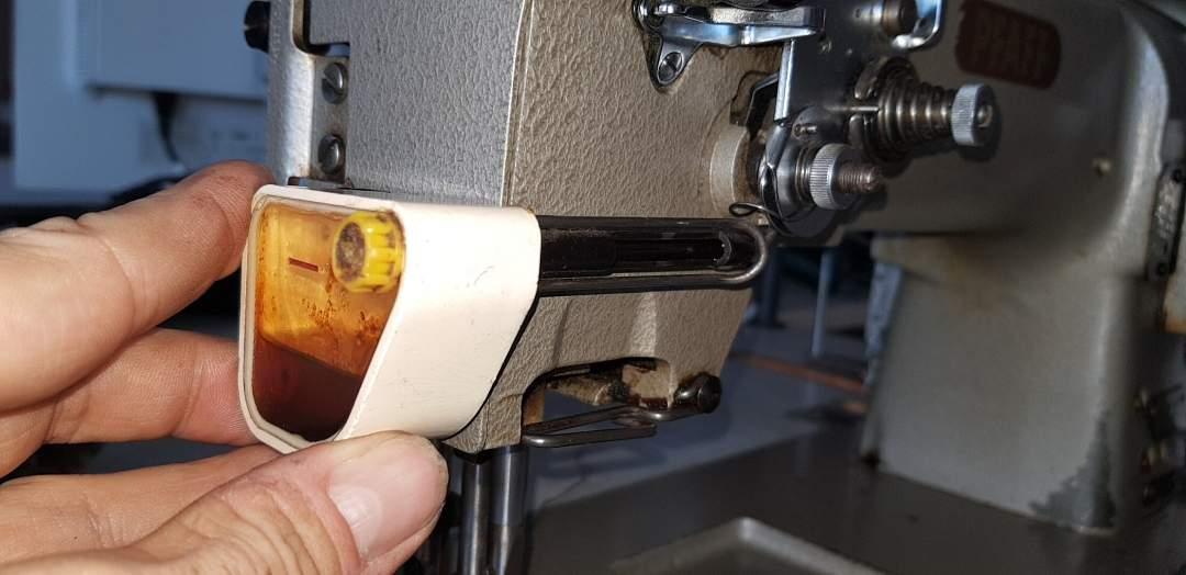
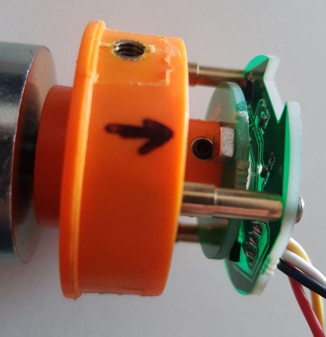
Hey guys, this little gadget came with my "new" Pfaff 545 today. It seems to be some kind of top thread oiler (with the wick missing). There's no brand name or the like printed on it anywhere. It attaches to the front plate of the machine with two bolts. I've never seen something like that before (besides the "bathtubs" on top of 45 or 29k's). Does anyone know anything about it? TX in advance, Pete...

-
Adler 104 stitch length - adjustment manual
Pterytus replied to Pterytus's topic in Leather Sewing Machines
Well, with me sometimes it's "personalizing" my machines - I just can't leave the things the way they are. And if I can improve things in the process (or at least don't make 'em WORSE ;-) then I'm likely to go for it. Now I do not have to adjust backwards stitch length once I change forwards stitch length. I know me: I'd just forget it and create "false" stitches while trying to lock a seam. Especially on leather I'd rather avoid that. Oh, glue is dried - so back to sewing X-max presents ;-D -
Adler 104 stitch length - adjustment manual
Pterytus replied to Pterytus's topic in Leather Sewing Machines
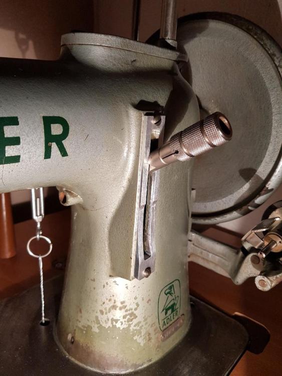
Okay, I just HAD to test it ;-) No 3D-Printer, no plastic. Metal it is - so it took some time but it came out ok, I think. Before, with the flat frame it was: short: F1.4mm/R2.1mm (50% off!) middle: F4.8mm/R5mm (that was the only SL-area which was ok) long: F9.7mm/R8.1mm I tried three different stitch lengths with the new SLL-frame F and R and they came out fairly equal: short: F1.9mm/R2.1mm middle: F4.6mm/R4.8mm long: F8.1mm/R7.9mm Which is enough for the 2-3 backwards stitches I usually need. So now I can rest!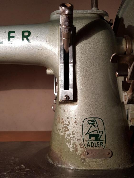
-
Adler 104 stitch length - adjustment manual
Pterytus replied to Pterytus's topic in Leather Sewing Machines
The main thing to find out was the "adjustable vs. built-in" problem. And because it seems to be built-in mainly (not that you could not make it even worse by bad adjustment) and cannot be cured with a screwdriver, the matter is kind of "solved" for me anyway. The work-around is independent from that. So thank you for your helpful input! Sure, I'd keep the original frame anyway and the plastic would only be to test if it works, maybe optimize it and finally build a copy from metal which lasts. I'm pretty happy with all-metal machines and would not add something plastic for real usage. ---- If I actually HAD a flux capacitor (and maybe a Delorean), I'd travel back in time and tell the Adler guys to place the damn pivot point in a better place to solve that problem once and for all - unless, that is, they'd put me in a loony bin, which is a far more likeley scenario... :-) -
Adler 104 stitch length - adjustment manual
Pterytus replied to Pterytus's topic in Leather Sewing Machines
Ah, I've been called much worse! ...and with reason ;-) And sorry, did not intend to give anyone geometric nightmares, they're THE WORST! Next time I'll just show you the (completely non-stochastic) formulae, btw., they're y_F=-0.021x²-0.433x+9.654 and y_R=-0.018x²-0.264x+8.082, that better? :-D Anyway, NOW would be a good time for a 3D-printer. Just to verify (or falsify) my madness. So it's metal-or-nothing for me now... -
Adler 104 stitch length - adjustment manual
Pterytus replied to Pterytus's topic in Leather Sewing Machines
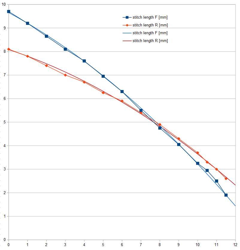
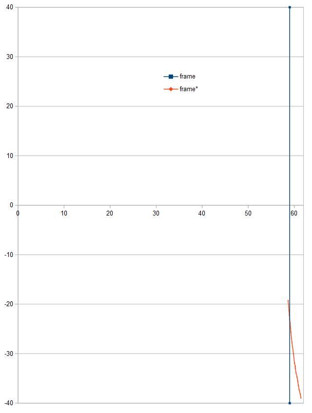
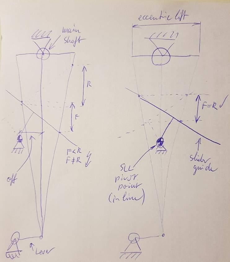
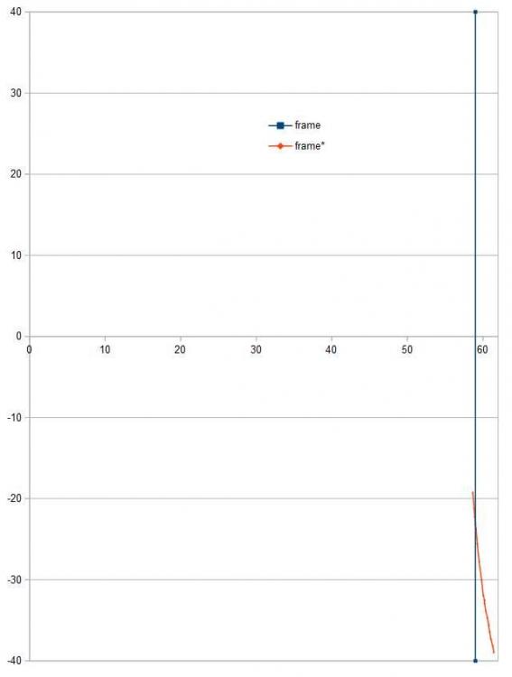
So I DID go a bit further and collected some data ;-) The first graph shows F and R stitch lengths in blue and red (x-Axis is number of revs of knurled SLL-nut) - measured data and approximated quadratic equasions to ease calculation. So if you reduce lever travel below the intersection at 5.2mm stitch length (F) accordingly you'd end up with equal stitch lenths F and R by just flicking the SLL up and down. The second graph shows pivot point of SLL (0|0) and flat SLL-frame surface at x=59mm in blue. Changing lower SLL-frame geometry from blue to red would result in the required lever travel reduction. True: You'd lose approx. 1.5mm F stitch length, because R only goes up to 8.1mm - which should still be ok. Maybe it's just a matter of opening up upper SLL-frame. This should be possible because the rest of the machine is capable of 9.7mm. The red line in the second graph is roughly a straight line so it would not even be necessary to machine some complex contour but just add some kind of wedge etc. to make the modification possible. I'm not sure if it really is necessary/worth to realize that in hardware (see above) but it seems realistic and not too challanging. Anyway I wanted to share my findings with you guys :-)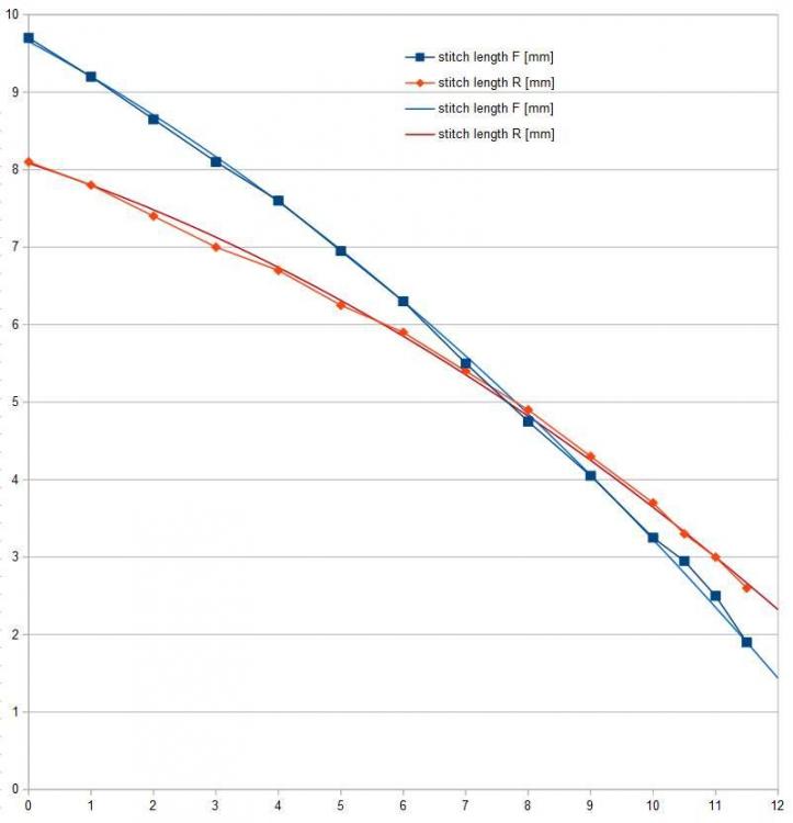
-
Adler 104 stitch length - adjustment manual
Pterytus replied to Pterytus's topic in Leather Sewing Machines
You're probably right ;-) At first I thought it was/is a matter of adjustment. In that case, I would have preferred to get it right. So maybe it got a little out of hand once I realized it is a built in "feature". But at least I found That out in the process, so I think it was worth discussing anyways. -
Adler 104 stitch length - adjustment manual
Pterytus replied to Pterytus's topic in Leather Sewing Machines
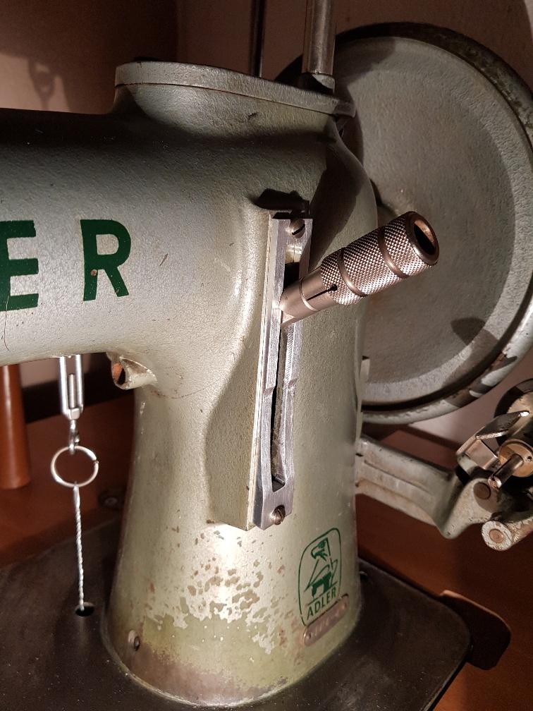
I think I'm "OK" with metal ;-) So I COULD in fact do something like that. But it would only partly solve my problem: On such a machine (late type or modified mine) you'd have to adjust R stitch length each time you change F stitch length, if you want it to be equal. Does not seem that practical - but in fact "solves" the problem for the company because noone can complain about, uh, what-I-do. So this could be (part of) the reason. So a real solution would be to design something like a curve which protudes more or less outward on the R (top) side of the SLL frame and limits the SLL in the correct angle to match F stitch length. With my data it would mean plus-material directly above 0 (center). Level-material at 5.2mm F stitch length and minus-material above 5.2mm stitch length. That way I'd only have to "flick the switch" in order to get correct (matching) R stitch length. I believe the problem is the pivot point position of the SLL relative to the direct line between the centers of the main shaft and lever connection of the fork (below the bedplate). If the pivot point would be in line with those two centers, F and R would be exactly the same (simple geometry). On my (the) Adler 104, the pivot point is significantly off this line to one side - maybe there is a good reason for that, but this seems to result in the observed behaviour (there's a draft attached, don't know if that helps to explain what I mean :-) It's the same on my Haid&Neu, but on a garment-sewing household machine noone really cares about unequal stitch length (or even recognizes it). If you work with leather it does matter. So if all that is true, it is not a matter of adjustment...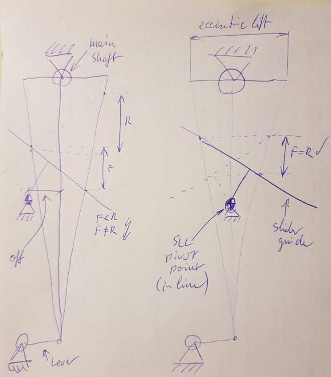
-
Adler 104 stitch length - adjustment manual
Pterytus replied to Pterytus's topic in Leather Sewing Machines
I checked the stitch lenghts F and R for different settings of the stitch length regulator and measured 10 stitch lenghts each. First test was full stitch length, the others were changed by full knureld knob revolutions, with zero (centered regulator) being 13 revolutions in. And the result is really interesting: 0: F97mm/10, R81mm/10 (-17%) 5: F77mm/10, R62mm/10 (-20%) 7.5: F52mm/10, R52mm/10 (+/-0%) 10: F33mm/10, R42mm/10 (+27%) 12: F14/10, R21/10 (+50%) So with my current setup there is ONE stitch length at ~5mm in which F and R stitch lenghts are equal. Longer stitches result in reduced R stitches, shorter stitches result in increased R stitches. Would be really interesting to compare it to an equal machine (sister 104-4 from the same production year). Or maybe there is something to adjust other than what I already tried. -
Adler 104 stitch length - adjustment manual
Pterytus replied to Pterytus's topic in Leather Sewing Machines
@Bert51 Yes, needle timing is checked and ok (I built myself something like this gauge). The machine sews ok with different needle and thread sizes, only F and R stitch holes do not match. @Constabulary I'd have to measure this to have the exact figures, but it's something like 10% off, I'd guess. And yes, it's in all lever positions. Otherwise I would not really mind (or would not have found out in the first place as 9mm is not my regular go to stitch length ;-) -
Adler 104 stitch length - adjustment manual
Pterytus replied to Pterytus's topic in Leather Sewing Machines
So I went through all the adjustment rules, but there seems to be missing something. The description tells you to adjust the eccentric on the main shaft (and I've done that). But that alone CAN NOT be the solution for uneven F/R-feed as it only synchronizes the needle position to the feed dog position. So let's remove the needle. The machine still transports the fabric (correct or incorrect). So the needle timing does not affect the feed kinematic in itself and thus can not cure the problem at hand. Next would be feed dog lift. Not relevant in this case, as it also does not affect the (in-plane) F/R feed dog movement which is the main problem (you might be able to deribelately shorten F feed to R feed length by a prematurely diving feed dog - but that's cheating). The key problem is visible with the machine in F when the feed dog is in its in-plane dead center nearest the back of the machine. When changing to R, the feed dog moves to the front of the machine but changes direction shortly before the stitch lenght regulator reaches it's end stop and moves a little to the back of the machine again. THAT is the "missing" R feed - which has nothing to do with needle timing or feed dog lift timing. It's a result of the internal stitch length regulator kinematic (slider position, pivot points etc.) and I'm not quite sure it can be adjusted - or maybe I am missing something... -
Adler 104 stitch length - adjustment manual
Pterytus replied to Pterytus's topic in Leather Sewing Machines
Great, thanx! Maybe the solution is somewhere in there. -
Adler 104 stitch length - adjustment manual
Pterytus replied to Pterytus's topic in Leather Sewing Machines
Well, I'd strip it, if only I knew where to start tweaking. Turning the eccentric on the main shaft does not do the job and I don't know where else to look but I'm pretty sure it's just a matter of adjustment somewhere somehow... On the furthest dead center of the feed dog (nearest to the back of the machine), there is nearly no gap in the stitch plate. And lots of gap in the stitch plate on it's nearest dead center (nearest to the front of the machine), so the feed dog seem to be off center by quite a bit. When the feed dog is in it's furthest dead center and I change from f to r the feed dog moves to the front first but goes a litte back in the end. This is the "missing" r feed travel. When the feed dog is in it's nearest dead center and I change from f to r the feed dog moves a little further to the front first and then all the way to the back, accordingly. I have a small smooth running Haid&Neu Torpedo which works pretty similar to the Adler design-wise (two or so notches down the size-o-meter). I think I will play with it a little to try and unterstand what's going on. If I get to the bottom of it on the H&N it's just a matter of bigger screwdrivers for the Adler. -
Adler 104 stitch length - adjustment manual
Pterytus replied to Pterytus's topic in Leather Sewing Machines
Ok, so it's not the wedge piece, which works the same 0° and 180°. The scale plate is worn only in certain areas (f/r approx. the same amount btw.). Test in worn and not-worn areas still result in different stitch lengths f and r. Adjusting the eccentric helped, but didn't completely equal out f and r feed (still 8.5f to 7.5r). Further rotation only results in backwards transport at the end of forwards movement - which can't be the solution, obviously. So a little nonconlusive here - but hey! Who wants to go Backwards anyway... -
Adler 104 stitch length - adjustment manual
Pterytus replied to Pterytus's topic in Leather Sewing Machines
Thanx, good points. The scale plate is a little worn, this shouldn't have too much of an effect cause it's not too bad, but I'm going to check that at first, also the wedge piece. If that's not it - which I expect - I'll have to adjust the eccentric trial and error style, I guess ;-) And yes, the check spring was misplaced (pretty obvious, now that I look at the picture again...). I corrected this when I tried to thread it (after the photo was taken) but thank you for the tip anyways. -
Adler 104 stitch length - adjustment manual
Pterytus replied to Pterytus's topic in Leather Sewing Machines
Right, it's the one with the early threaded metal adjuster knob, oh, and it's a -4 subclass.
-
On my machine forwards and backwards stitch length are not equal, so when changing direction the stitch-holes do not match which is not very good for locking stitches etc. So is there an adjustment manual for the Adler 104/Adler 4 (w/o needle feed) available out there somewhere? Quick fix would be if someone could tell me how to adjust this. I only have adjustment manuals for compound feed machines which work differently.
-
Anyone using a servo motor with needle positioner?
Pterytus replied to gavingear's topic in Leather Sewing Machines
The double magnet mod on my Aerostar Servo Sensor still works fine... ;-) But for my big Adler I ordered another brand of Servo with a differnt Sensor type. It's a 750W Jack Servo and the (big) Sensor it came with is not magnetic as on the Aerostar but optical with two slotted discs inside for upper and lower needle pos. You can adjust (rotate) the discs to match the exact needle-positions you want. My setup also includes a speedreducer but there does not seem to be any restriction in terms of transmission rato, at least with my 0.215 overall transmission ratio (motor to machine) everything works fine without mods. The Jack seems to generate less vibration but starts at 200rpm as opposed to the Aerostar which starts at 100rpm. Both 750W and they cost about the same by the way. -
Servo motor running rough at low speed
Pterytus replied to DanishMan's topic in Leather Sewing Machines
With my aerostar 750W, I had a similar problem at low speeds. The roughness/vibration problem was much less bad when I disabled the sensor in the software. Although this does not solve the problem when you actually want to use the sensor, it might be interesting to see if your servo behaves the same. In the end, my solution was to add a speed reducer. The motor now runs at higher speeds without roughness and top speed is still fast enough for me, but that is personal choice. -
Hey guys, I am looking for the instructions sheets/manual for the Aerostar JM822 Servo Motor in English. Does anyone have those avaliable? Already asked the question "hidden" in another thread, so I'll try separately in the hopes of heaving more luck here ;-) TX
-
Servomotor - Speedreducer - Needlepositioning/EPS
Pterytus replied to Pterytus's topic in Leather Sewing Machines
You are right, this time-needed-to-slow-down issue came to my mind as well. Maybe the controller DOES learn the exact degrees of the machine and determines when to begin slowing down in order to stop at the desired position - which would make sense, although a little more sophisticated software-wise than just stopping at the signal. With my deliberately slow machine it would not make that much of a difference, I think. Well, the sensor-chips inside the sensor-module Are 180° offset (see picture above). However, if the controller DOES learn the number of motor-revs needed to make one revolution at the machine, it actually COULD stop earlier or later. And you would want it the way you described and not exactly half a revolution offset. The German manual to my JM-822 is not very helpful (baaaad translation and just a few words as description) but I think there is a menu item to adjust the TDC and BDC needle position. Up to now I did not dare to change these settings ;-) But now that the NPS seems to work it might be worth a try. By the way: Does any of you guys happen to have an ENGLISH manual for the Aerostar JM-822? I think that might clarify some of the menu items - the combination of two bad translations should be better than just one, right? :-D -
Servomotor - Speedreducer - Needlepositioning/EPS
Pterytus replied to Pterytus's topic in Leather Sewing Machines
In case your needle stops in down position (BDC) unwanted, just give your pedal on (really) short tip with your toes and it should move up (TDC) because the controller "thinks" you want another full revolution, which - in case of two magnets - means half a revolution of your machine in reality. Fortunately it would never rotate MORE than wanted, only sometimes half a revolution less than wanted, which can be "corrected" by another half revolution. Heel down should only reverse what happend previously. If it stopped in BDC, heel down should move it up - if it stopped in TDC, heel down should move it down. As in: Rotating forwards till the next detection of a magnet signal at the BDC-sensor-chip. Not perfect, I admit, but maybe it helps you to "deal" with it. -
Servomotor - Speedreducer - Needlepositioning/EPS
Pterytus posted a topic in Leather Sewing Machines
When I updated my aerostar JM-822 servomotor driven machine with a speedreducer (see: this modification resulted in the EPS/needlepositioning not working any more, the controller froze with an error message. This seems to be a common problem once the overall transmission ratio exceeds a certain limit (usually by adding a speedreducer). User Captayne already posted his solution, which resulted in alternating TDC/BDC-needle behaviour when stopping the machine. https://leatherworker.net/forum/topic/6 ... ent=467360 So I took a look inside my sensor module (Zhejiang Aerostar JM-822 750W) and found two sensor-chips (one each for up and down) and one magnet mounted on the rotor-PCB, which features two mounting-holes 180° opposite to each other, so one is left blank. I glued a second magnet on top of the PCB in position of the second blank hole (180° offset) in the same N/S orientation as the original one, put it back together and replaced it on the machine. In the controller setup there is a menu item N.B: "synchronizer type", which can either be set to "1" or "2". After setting it to "2" the EPS system works perfectly again. Releasing the pedal will move the needle to BDC (down), pressing the pedal backwards will move the needle to TDC (up) just as desired. So if you have the same (or a similar) setup and the EPS does not work properly it might be worth taking a peek inside the sensormodule as well...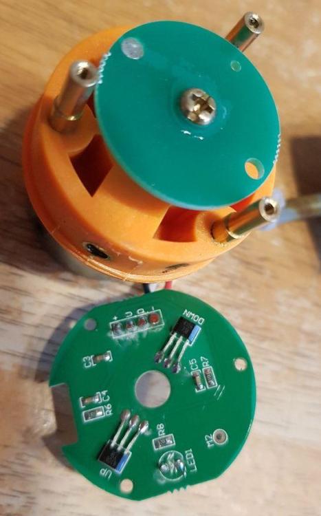
-
Large bobbin (0f 5XX series) in Pfaff 145
Pterytus replied to Pterytus's topic in Leather Sewing Machines
You are right, those parts are needed. Fortunately I do have a complete 5XX series machine (541) with all those parts and could "just" swap them while still keeping the 541 operational afterwards (with a smaller bobbin). Most of those parts however are bolted on and can be removed, replaced and adjusted using a screwdriver that's why dismounting/moving the bushing was incalculable for me at first. Cheers, Pete... -
Large bobbin (0f 5XX series) in Pfaff 145
Pterytus replied to Pterytus's topic in Leather Sewing Machines
Ok, so I have this Pfaff 143, which was ridiculously cheap and out of tune but came barely worn and with some parts missing or in worse condition on my 145 and 541, so it became my "bad-part-accumulator-machine". It's still in working condition but it's, well, just a 143, what else can I say ... ... which makes it a perfect lab rat. First I tried to "pull" out the oil pipe from the top of the bed plate - which was not possible without much force so I left it there hoping it doesn't lock the bushing. Then I removed the grease housing and large bevel gear on the hook driving shaft which would otherwise prevent the bushing from being moved to the left and heated up the bushing and bedplate in that area to a point where I could barely touch them. I then used a hammer on the bushing from the right with still reasonable but real force which - Ta-Dah! - forced the bushing bit by bit to the left. So much for the experiment. I hammered it back in place, replaced all parts and adjusted the hook so that the machine works again - no harm done. But now I know how to remove the bushings. I just have to decide whether I really want to perform that kind of blunt treatment on my machines or if I can live whith the smaller bobbin in my 145, but at least I now know that and how it can be done. So thanks for your input which helped and encouraged me to try and learn a little more about the machines. Cheers, Pete...