Ian1783
Members-
Posts
112 -
Joined
-
Last visited
Content Type
Profiles
Forums
Events
Blogs
Gallery
Store
Everything posted by Ian1783
-
Pedal for Servo Motor? Mine is missing.
Ian1783 replied to Ian1783's topic in Leather Sewing Machines
I see, and aligned more vertical with the pull-point on the motor's lever. Makes sense. Ian, SF Bay Area -
Pedal for Servo Motor? Mine is missing.
Ian1783 replied to Ian1783's topic in Leather Sewing Machines
Thank you all for the feedback! And Yetibelle, that's a great suggestion! It's true that mine has an older look, and the cast-iron may match well, provided it attaches properly. Greg, your suggestion looks to be what I recall as my table's original pedal. Just what are those "extensions"? Do they go from the pedal to the motor? I have a link-chain that I'm sure is for the presser-lift pedal. I also have a rod with hook-end, with a clamp that I think is meant to hold two rods (for length adjustment), but I'm missing one of those rods. Ian, SF Bay Area -
Pedal for Servo Motor? Mine is missing.
Ian1783 replied to Ian1783's topic in Leather Sewing Machines
Are they something Toledo carries, or are they more an item I'd have to source through the catch-as-catch-can parts community? I'll only need the motor-pedal, as my wife seems not to use the knee-lift on her Chandsew, and would probably have no use for the foot-lift on this machine. Ian, SF Bay Area -
My Singer 153W103 came with what I figure must be an older table. It is much more light-weight than the K-leg table for my Chandsew. As can be seen in the photo, it uses a tubular bar for its pedal support, but I don't have the pedal. Can the original pedal-type be found easily (and cheaply) enough, or is there some option for a pedal replacement when i get a servo motor for this machine? Ian, SF Bay Area
-
Singer 153W103 Cylinder Repair and Timing - Pics
Ian1783 replied to Ian1783's topic in Leather Sewing Machines
Thought I'd tie this thread up with a couple of "after" photos. I've only been able to "dry fire" this machine. It's advancing material as it should - thanks to Uwe's videos showing what I need to look for. As it turns out, I don't have the proper bobbins for this machine, so haven't tested it with thread. There are a few other parts needed: a thread guide (the lower of the two at the thread tensioner), and maybe a few new screws to replace those whose heads are rather worn. I'll have to order a servo motor setup from Toledo, but even before that, I'll have to source pedals for the stand. There are two that are used, one for the moor and one for the presser lift. That should put me into usability territory. There may be an issue with the hook to needle adjustment, as I have the hook as close to the needle as the hook guard will allow, but it seems not quite close enough. Though, if it works well, I won't worry about that. Lastly, I'd like to encourage anyone thinking of making similar repairs to do so. I learned a lot and enjoyed it all. I picked up the machine about 3+ years ago for $150, and with another $100 in parts, I may have a machine that will work well for a good many years. Thanks for all the help! Ian, SF Bay Area -
Singer 153W103 Cylinder Repair and Timing - Pics
Ian1783 replied to Ian1783's topic in Leather Sewing Machines
That's the video I mentioned! It has really helped me understand much of what I need to know. Thanks! I had the idea of looking for images of this machine online, and found a few that allowed me to guesstimate where things needed to be (one of them, the one that really helped, was one of MADMAX22's - thanks MM22!) Your further instructions above helped ice the cake, Uwe. I can see that I'm pretty much back to where I was before loosening that screw (what I call "All part of the learning process - doh!"). Thanks again! Ian, SF Bay Area -
Singer 153W103 Cylinder Repair and Timing - Pics
Ian1783 replied to Ian1783's topic in Leather Sewing Machines
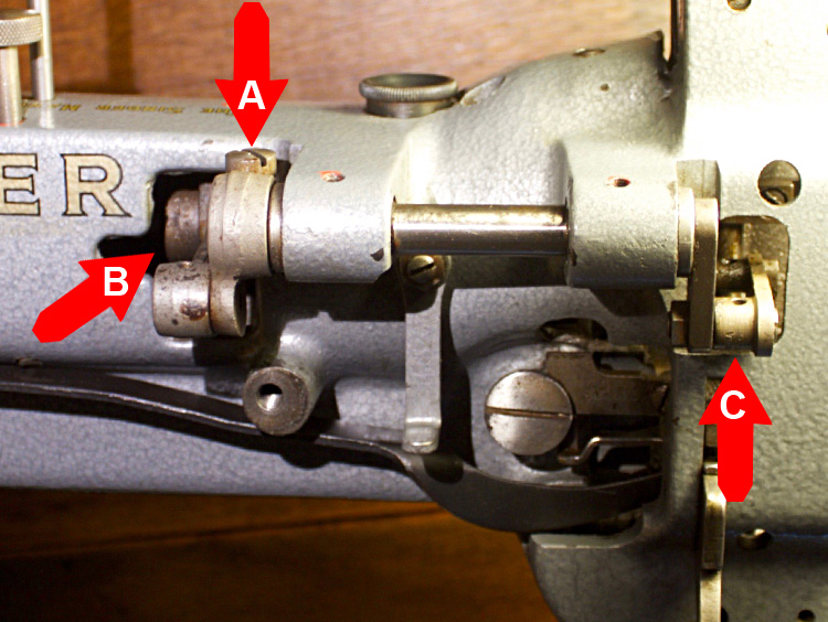
OK - new issue! I'm now trying to adjust the presser feet. I have had some luck in understanding the process and did make a few adjustments that seemed the right ones. However! I loosened the screw (A) on the shaft that actuates the presser feet, and now I'm having difficulty grasping the process for getting back to square one (or, ideally, to where I want to be: with presser feet properly timed to the feed dog and each other). I'm trying to find a correlation between two parts: the position of the shaft (B) (and so, by extension, the position of the arm in the body of the machine that activates it) and (C) which is where it all comes together in the timing of the presser feet. I'm again looking for an equation that has part (B) in a specific position, so that part (C) can be adjusted to be in proper time with it. I'm stumped. Granted, I may get it eventually, but it's a real head-scratcher. There is a three part correlation where all three points depend on each other for the whole to work properly. I haven't found anything in the manual that pertains to this adjustment. Ian, SF Bay Area -
Singer 153W103 Cylinder Repair and Timing - Pics
Ian1783 replied to Ian1783's topic in Leather Sewing Machines
Before beginning further adjustments today (and before that, continuing the process of acquiring the knowledge to do so), I've been Googling Walking Foot Adjustment, and found not much info. But I did find a Youtube video that, while for a Juki LU-563, was just the type of online instruction I felt I needed. I bookmarked the "page" and had every intention of sharing this link, as I was very impressed with its production quality. Only then did I notice, Uwe, that it was one of yours! Excellent instruction; great visuals. Remarkable that so much information can be shared without a single spoken word of dialog (clear text of the step by step instructions is used). -
Singer 153W103 Cylinder Repair and Timing - Pics
Ian1783 replied to Ian1783's topic in Leather Sewing Machines
Uwe - Perfect! Well, this is a much clearer manual than one I was using, and quite a bit more complete. Now it will be a matter of understanding what I'm reading. I have made progress, though. Trial and error progress, to be sure. I've been able to to adjust feed dog timing to match the needle. That took hours. Now, I'm hoping your instructions include those for adjusting that cam, which times the proper up-and-down motion of the feed dog. Edit: To be clear, that cam does indeed time the feed-dog's up and down motion, but it is in relation to the position of the needle, and, I presume (I haven't got that far) the vibrating presser foot. I need to know just when the feed dog should be just rising above the needle plate - and, by extension, just when the feed dog should clear (fall below) the needle plate. Or, as a perhaps simpler way to put it: when the cam lobe is in its full position (feed dog at max height), where would the feed dog be in its back-and-forth position? The manual does not appear to include the instructions for timing the cam (unless I'm missing something, which might certainly be the case). I'll tackle this tomorrow. Thanks! Ian, SF Bay Area -
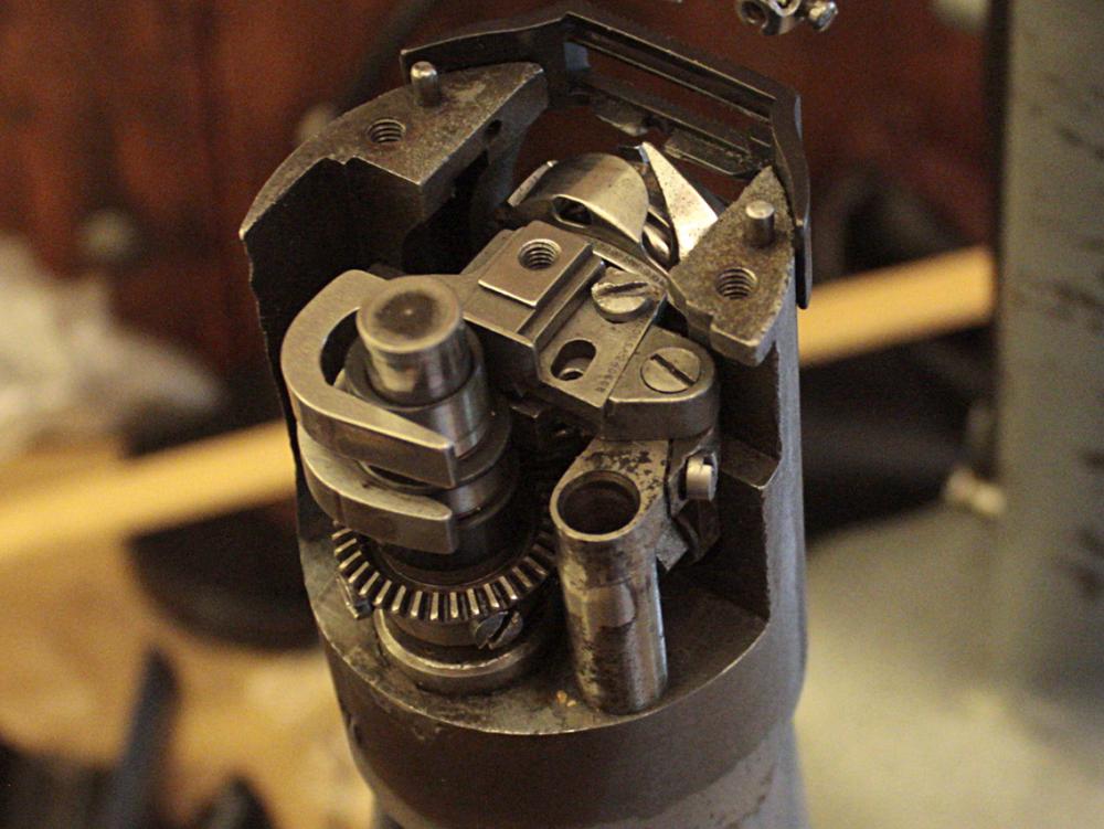
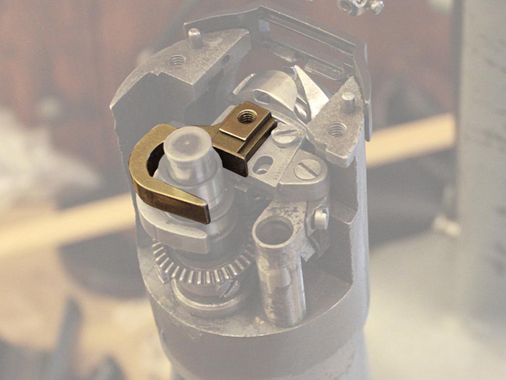
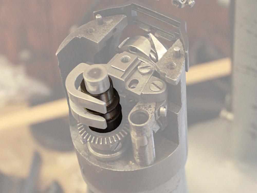
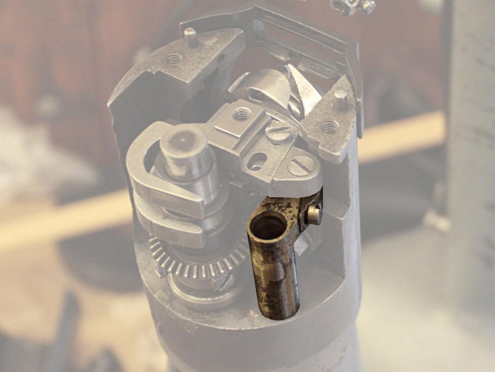
I'm in the process of essentially rebuilding the feed-dog mechanism of my 153W103, having purchased new parts, now installed, but that await proper adjustment. I'm hoping someone might have input on where to start with with timing of the feed-dog mechanism. This machine suffered what appears to have been a catastrophic failure that resulted in a few broken parts. The hook timing does not appear to have been affected (and that's fairly straightforward). I've replaced the parts, but must now time the up-and-down movement of the feed dog, as well as its back-and-forth movement. I'm hoping for that instruction that states, in so many words, something like: "With Part A aligned with Part B, ensure that Part C is aligned with Part D". In the above example, I see "Parts A and B" being a hook-timing position (my starting point, unless I'm shown that I should start with some other starting-point position) with Part C (in my case, the cam that activates feed-dog lift) needing to be properly positioned when Parts A and B are in said starting-point position. At this same time (if things are as simple as this), Part D (if you will), the Rock/Lift Shaft, should be at 'such and such' position. Sorry if this is asking for a bit much. In my mind, it seems a rather simple equation, and I may just get there on my own, but I would think a service manual (as opposed to an operating manual), which I don't have, would show these correlations. That would sure simplify the process for me, and save me from having to "reinvent the wheel" in terms of the detective work required. I'm including photos, and hope that these may help clarify my issue, as well as provide some resource for anyone contemplating the same adjustments on a cylinder-arm machine of their own. I'd be happy to provide more photos, and I'm at that point where most of what I've done can be undone to any stage for further visual clarification. In short: I need help in understanding the timing of the feed dog as it relates to the cam and rock/lift shaft. First image is of the area in question. Second image shows the cam-activated feed-dog lift (I need to time the lift). Third image shows the cam that activates the feed-dog lift (this is what I need to adjust and lock in place). Fourth image is of the rock/lift shaft that provides the back-and-forth movement of the feed-dog (this also needs to be timed and locked in place). Thanks in advance for any help you can provide. And, please, if you're in the same boat, ask of me any questions you might have - I just may have some insight after having got this far with my project! Ian SF Bay Area
-
Need parts for Singer 153W103 Cylinder Arm
Ian1783 replied to Ian1783's topic in Leather Sewing Machines
Thanks, Uwe, for the quick turn-around on the parts! They arrived yesterday. I'll no doubt be posting about how this project proceeds, now that I have the parts to ensure a big step in the right direction. Ian SF Bay Area -
Need parts for Singer 153W103 Cylinder Arm
Ian1783 replied to Ian1783's topic in Leather Sewing Machines
Just as a matter of course, Bob, I should have contacted you, as I have done business with TI before, and, as I'll end up wanting another servo-motor setup from you to drive my machine, I'll be in touch! Ian SF Bay Area -
Need parts for Singer 153W103 Cylinder Arm
Ian1783 replied to Ian1783's topic in Leather Sewing Machines
For the benefit of others in my position, that of needing help with parts and info for, in this case, a Singer 153W103, I'd like to acknowledge both Eric and Uwe for their quick responses to my inquiries. I'm sure I'll be getting back to the forum with other questions and comments, and perhaps the news that I've successfully brought "back to life" a notable machine. Ian SF Bay Area -
Uve,
Thanks for the offer! I'd like to take you up on that. Are the parts readily available, do you think? I'm afraid of going through the time and expense of getting ahold of some, but not all. I'd then be no closer to a working machine.
As I've mentioned, these are the only parts I've found that need replacing, but after installing them, I may find I need another - do you know if parts are so readily available that I can get back to you should the need arise? That'd be awesome.
How best to go about ordering from you?
Ian McInnis
137 15th Ave, San Mateo, CA 94402
(650) 759-0287 imcinnis@comcast.net
-
Need parts for Singer 153W103 Cylinder Arm
Ian1783 replied to Ian1783's topic in Leather Sewing Machines
Very cool, Eric. Ian -
Need parts for Singer 153W103 Cylinder Arm
Ian1783 replied to Ian1783's topic in Leather Sewing Machines
Thank you, again, Eric. There are, as far as I can tell, four broken parts that need replacing: #240600 (I believe that's what the number is - part is broken right through the part number) #240607 #240688 #233614 I don't yet know if I need other parts (to be sure, I need a bit to put the table together, including a servo motor setup), but these are those I certainly see as broken. There is that one other part (#230576) that I believe is OK, though looking like an incomplete ring. If you could give me a price on what you have, and how I'd go about purchasing those from you, I'd very much appreciate it! I'm attaching an image that I've used before. Ian -
The above link is to a topic I started a few years ago. It still applies! Yes, I got into other projects and let this one slide. I'm now hoping to pick up where I dropped off, rather than merely stumbling across this nice machine and doing nothing about it. I'm sure my wife could make use of a cylinder-arm machine (she's using a flat-bed Chandsew RB 406). I'm hoping to locate the parts shown in a few of the pictures in this thread - there are parts numbers there as well. I had good feedback in terms of how to understand what's going on here, but I really need to parts to continue. Eric (gottaknow) mentioned that sponsors may have the parts I need. Any help identifying those sponsors? I've been going over the machine today, and must say it all looks quite doable as a DIY projects. I've worked on any number of machines, have the patience, love to tinker, understand the need for proper adjustments, etc. Just need the parts to get this baby "back on the road". I'd also like to extend my best wishes to all on this site. I haven't been here for a couple of years. I hope all are well. Many thanks! Ian
-
Craigslist estate-sale item. No model number in the posting. What is it? Ian SF Bay Area http://imcinnis.blogspot.com/ OK then... would help if I posted the pics!
-
That's Impressive! I have, at least, some confidence that a hair blower may come in handy. Thanks for posting that. Ian SF Bay Area http://imcinnis.blogspot.com/
-
Thanks for the tips! I'm sure we won't be steaming our leather, though that, along with benlilly's suggestion of a heat gun, seems like an interesting idea. Perhaps I'll experiment with a blow dryer. Dwight's suggestion for hanging sounds doable. I recall delivering a machine to a local crafter who had her leather draped over dowels that were stacked like ladder rungs (though about six feet wide) on one of her work-room walls. I didn't give it much thought at the time, but can see where it might prevent wrinkling. Our leather comes to us rolled up, for the most part. But it's often been folded, due to size, before rolling. I just last night re-rolled some of what we have, just to see if that will help "iron out" some wrinkles. If not, then hanging over dowels will be the next test. Much of what we get are hides from which a choice section has been removed. The leftover being folded, rolled, stored, then eventually recycled (which is where we come in) if found unsuitable for further projects. No great care is taken to prevent folds and wrinkles in pieces destined for recycling. Ian SF Bay Area http://imcinnis.blogspot.com/
-
We have leather from a furniture maker that has been stored in rolls. There may be just the one large piece, or many smaller pieces, to a roll. They've been stored for two or three years (some more, some less), and have developed wrinkles and fold marks that we'd like to get out before sewing (small bags, aprons, pillows, etc.). Is there a good way to remove wrinkle and fold marks? What is the best way to store leather? We have a very small hobby operation just beginning out of our home; we don't have a lot of room, and this leather is a space hog. Ian SF Bay Area http://imcinnis.blogspot.com/
-
I visited a local supplier of leather goods and hardware, including rivets, and had something of an education. My wife was looking for a particular rivet and showed me samples of what she wanted. Turns out, these were the same rivets (in this case, "Quick" or "Jiffy" rivets) that we've used, though not without some problems. We were using a setting tool that was meant to maintain the domed appearance of the rivet as it came out of the package, when what we wanted was the flattened look that we'd seen examples of on different vintage bags. Following newly learned techniques, and keeping in mind the advice offered here, I successfully set a couple of rivets in the manner needed for the results we were looking for. I used only a hammer and metal surface (in this case, a small bench vice with anvil top). This is for the Jiffy Rivets, not the copper. I still have to make that attempt. As mentioned, it's clear the work surface matters. Thanks for the tips on work bench styles. I will have to put something together. Ian SF Bay Area http://imcinnis.blogspot.com/
-
Singer 29-4 "patcher" Needle Plate Question (Photo)
Ian1783 replied to Ian1783's topic in Leather Sewing Machines
Thank you all! It now makes sense, whereas before, that jumping bobbin case struck me as odd enough to worry that something was wrong. Ian SF Bay Area http://imcinnis.blogspot.com/ -
The needle plate on my 29-4 Patcher has two differently sized needle holes. I'm sure the idea is that the larger would be for larger needles, and the smaller for smaller needles. But what interests me is that on that side of the needle plate with the larger hole, there is an indented area above the bobbin case, but not one above the side with the smaller needle hole (pleas, see pic). I have noticed that the bobbin tends to "jump up" under this indent as if there is too much room above the bobbin, thus allowing for this movement. It does not seem to effect the stitch. Anyone with an idea of what that indent is for and how to utilize it and the different needle holes? Ian SF Bay Area http://imcinnis.blogspot.com/
-
Electrathon - Stable, yes (the cement floor), and very solid. So, I suppose I'll have to relocate to my garage for rivet setting. Randy - I've heard others mention a steel plate, and this sounds like the way to go: steel plate on heavy table (on cement floor). Camano - Thanks for the tip on newer vs older Tandy setters. I'll keep an eye out for the right tools. And to all: We've been setting copper rivets on leather aprons (for woodworking, gardening - with an order for one for iron working) with the flat side out (visible), peened-post side in. As one apron has a smaller pocket over a larger pocket, and its stress points riveted, there is a rivet - peened post on the inside of the pocket - to which a hand in the larger pocket comes into contact, and so our concern for sharp edges. I had not done any real research that may have exposed me sooner to the idea of having peened post on the outside. I was looking for a more pleasing look and thought the peened side should be hidden. Now, I see where a properly domed post-over-washer can have the effect of pleasingly-obvious handiwork as in your photo, camano. Ian SF Bay Area http://imcinnis.blogspot.com/


