


Snakeoil
-
Posts
82 -
Joined
-
Last visited
Content Type
Profiles
Forums
Events
Blogs
Gallery
Store
Everything posted by Snakeoil
-
Yes Mike, I have that manual. But I'm going to compare your copy to mine to see if yours has anything that might be missing in mine. Con Gusto, Jimi. regards, Rob
-
First, for clarity purposes, I'm going to use the following 2 terms in what I'm about to say. Pages - These are the numbered pages in the manual Sheets - These are the scanned images, each showing two pages in the PDF file. I scanned the pages as they were originally printed. I oriented them in the scanner so that they should directly overlay each other when using 2-sided printing. If you print the scanned sheets using 2-sided feature, you should be able to cut the 2 sided sheets, fold them, stack them and staple them in the middle to reproduce the original manual. I realize that this might not be clear, so here are a couple of examples. The cover (which I suggest you print on card stock, is made up of the sheet showing the front and back of the cover and the sheet showing the inside front and inside back of the cover. The inside front talks about the importance of good oil and needles and the inside back is a needle and thread chart. Print those two sheets as a 2 sided document and you should get a perfect cover that you can trim and fold. The first two pages of the manual do not have page numbers. So lets use page 3 as the example. Page 3 is printed on one sheet of paper with Page 26. On the other side of that sheet is Page 4 and Page 25. Print the sheets with those pages as a two sided document. I scanned the pages in the correct order so they could be printed as 2-sided sheets to make the booklet. To make things easier, here are the 2 pages that belong on each side of each 2-sided sheet. Side 1 Side 2 28, 1 (no number, title page) 2 (no number), 27 26, 3 4, 25 24, 5 6, 23 22 (blank), 7 8, 21 (no number, section title page) 20 (blank), 9 10, 19 18, 11 12, 17 16, 13 14, 15 (these two pages are the center of the booklet) regards, Rob
-
Thanks. Manual sent. Rob
-
I just made of my original 29K70 Manual. This came with my machine and says "Printed in Great Britain". For printing purposes, the manual measures 3-1/2" wide and 5-3/8" high. The staples were rotting away so before I restapled it, I took it apart and scanned it so that you could print out the pages using 2-sided printing and then stack and staple them to get the original manual. You could print the cover on cardstock for a stronger cover. Unfortunately, it is 7.38mb file so I cannot attach here. I'll look for a site where I can post it for download. I think tinyurl might work. Facebook might be another option. Rob
-
And the problem is back.
-
Just logged out and logged back in and it worked fine. But tried my phone and still an issue with the clock sync.
-
Still a problem on my end as well.
-
Looks like more than just an expired cert. When I try to access the site via my smartphone, it tells me that my phone's clock is wrong and unless I sync it with the site clock, I cannot enter the site. That never happened before and started the same day that the expired cert warning started showing up on my computer. Rob
-
For the past two days, when I try to come to this site, I get the following warning: There is a problem with this website’s security certificate. The security certificate presented by this website has expired or is not yet valid. Security certificate problems may indicate an attempt to fool you or intercept any data you send to the server. Rob
-
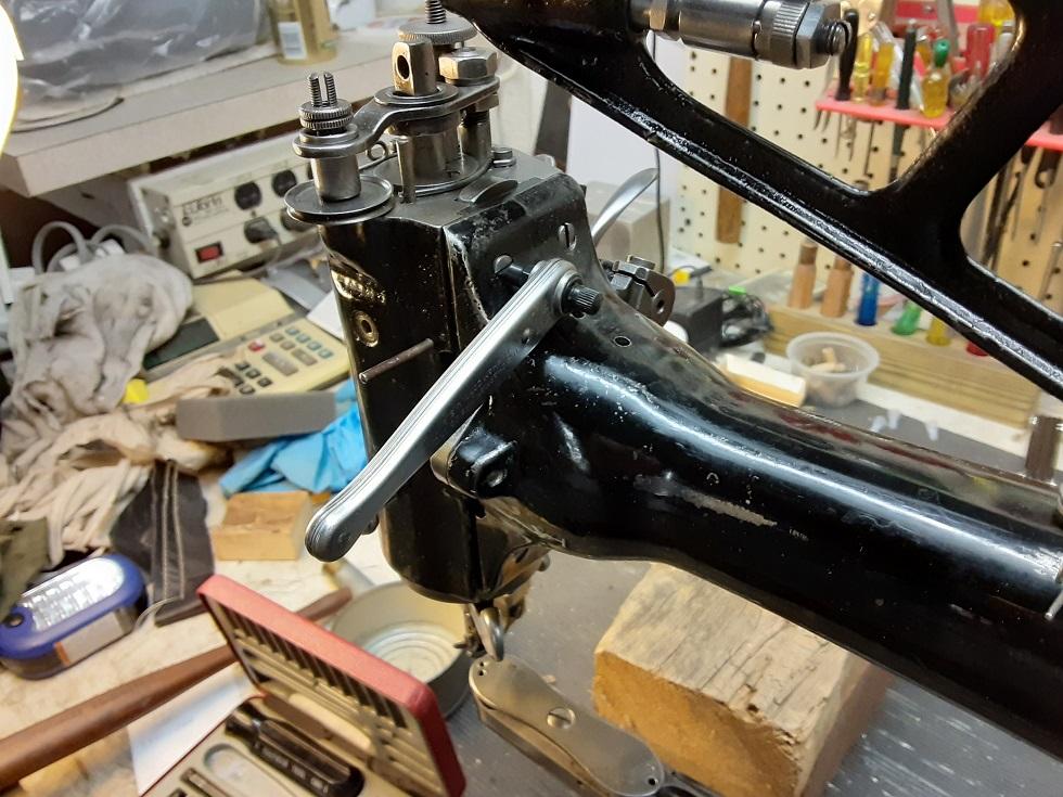
First a tip on removing the head. The four screws that hold the head to the upper arm are not easily accessed with a screwdriver. Yes, you can get to them, but it is not a straight line shot and if they were put in by Arnold or have some corrosion, you might damage the heads trying to get them loose. Here is a method that reduces the risk of damage while increase the torque you can apply to the screws. I'm using a Chapman Screwdriver bit in their small ratcheting handle. You can apply pressure to the screwdriver bit by pressing on the end with your thumb while cranking on the ratchet handle to break the screw free. I pulled my head off after putting my gearbox back together. I measured both the roller and the cam groove and they are just about a line fit, meaning near zero clearance. So no need for replacement. This is simply a follow up to my previous thread on restoring OEM stitch length. regards, Rob
-
Here is a pic of the bushing. Note that this bushing is not shown in the 29K70 Parts Diagrams. But it is show in the 29K71 Parts Diagrams. I'm wondering if my machine was rebuilt with a K71 gearbox or if later K70 machines had many of the K71 upgrades/features. The part number for that bushing is the K71 part number. So, let's put it back together. You can refer to the photos above for the reassembly process in addition to what I post below. The site is limiting me in how many photos I can post. So, it looks like I'm done with any new photos. But I think we have all we need anyway. First, put the Shuttle Carrier in place and slide the Driving Pinion onto the shank of the Carrier. Make sure you light up the threaded pin hole. The big end on the Carrier shank should face the hole in the Driving Pinion. I would start the screw a thread or two into the pinion before you assemble the two parts. The slot/hole in the gearbox will give you clearance for the screw sticking out of the pinion. Carefully screw the Pinion screw into the Driving Pinion and Shuttle carrier. Go easy. If it stop rather than enters the Shuttle Carrier, recheck alignment or twist them a tad relative to each other until the screw threads into the Carrier shank. If you force it, you will ruin the screw. No ham fisted machine techs allowed here!! With the screw home and snug, and snug mean snug, not Harley axle bolt tight, turn the pinion until it is position as in the photo above showing all the parts installed in the gearbox. Rotate the hand wheel until the Long Rack is just entering touching the Driving pinion. Then insert the Following pinion onto its shaft with the flat side of the pinion facing the cover plate (down). With that in place, insert the Short Rack and the gearbox is now assembled. It should look like it does in that same photo. Note the symmetry of how the parts are arranged. Now insert the Needleplate pin, which is called the Locating Plunger into it's hole with the pin end upward. Push it all the way in and then insert the spring behind it. If you did not oil parts while installing them, give all the parts a good squirt of oil. Now position the coverplate over the gearbox and align it so the Following Pinion shaft come thru the hole in the coverplate as you compress the spring and place it tight against the gearbox. Insert the right screw while holding the coverplate in place and snug it up. You can let go of the coverplate now and insert the other screw on the left. Just snug those screws. You are done! I was going to show you how to use that little Chapman ratchet handle but the site limit has been hit for photos in a thread. So, I'll start another thread about removing my head and show you there. regards, Rob
-
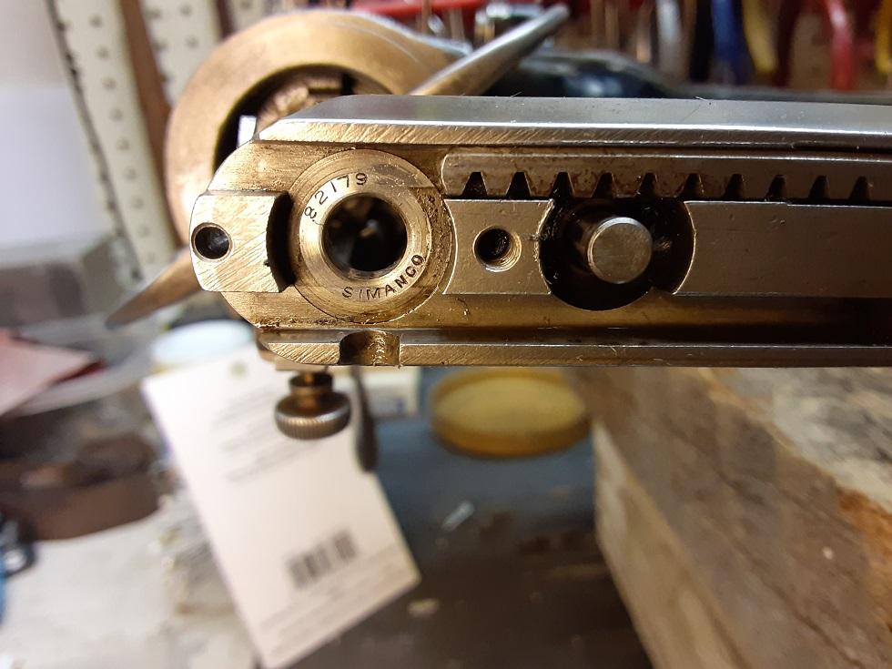
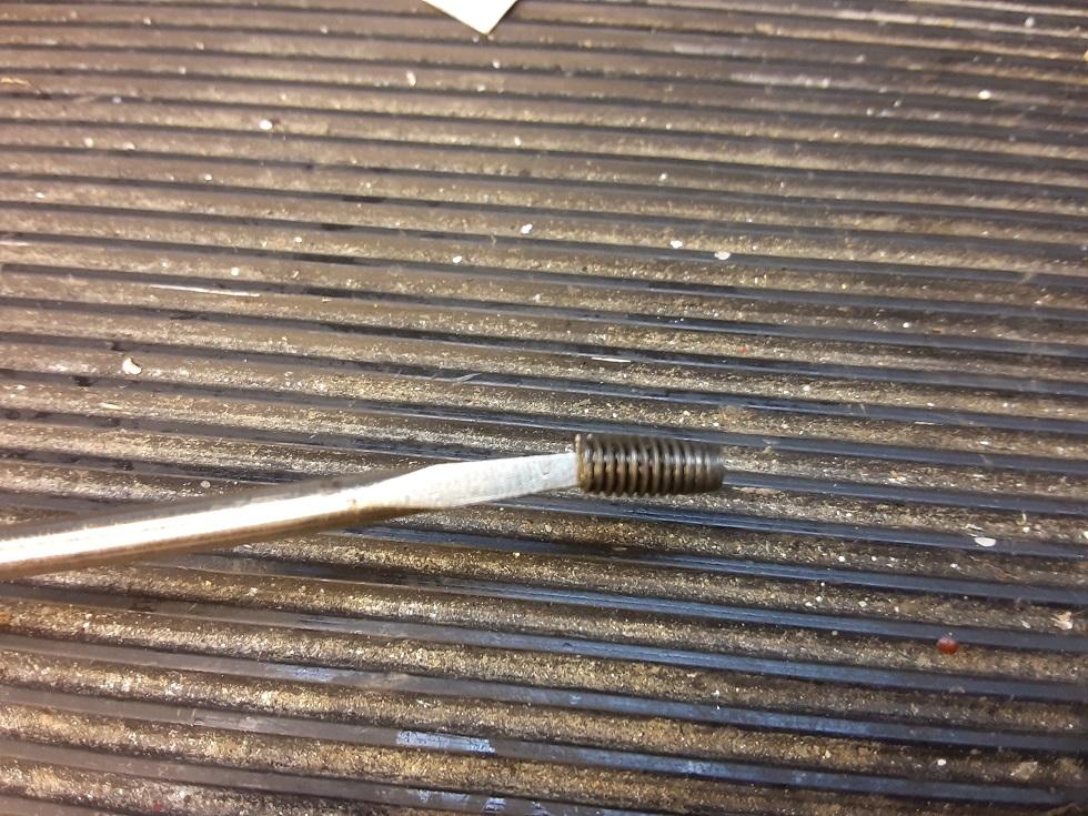
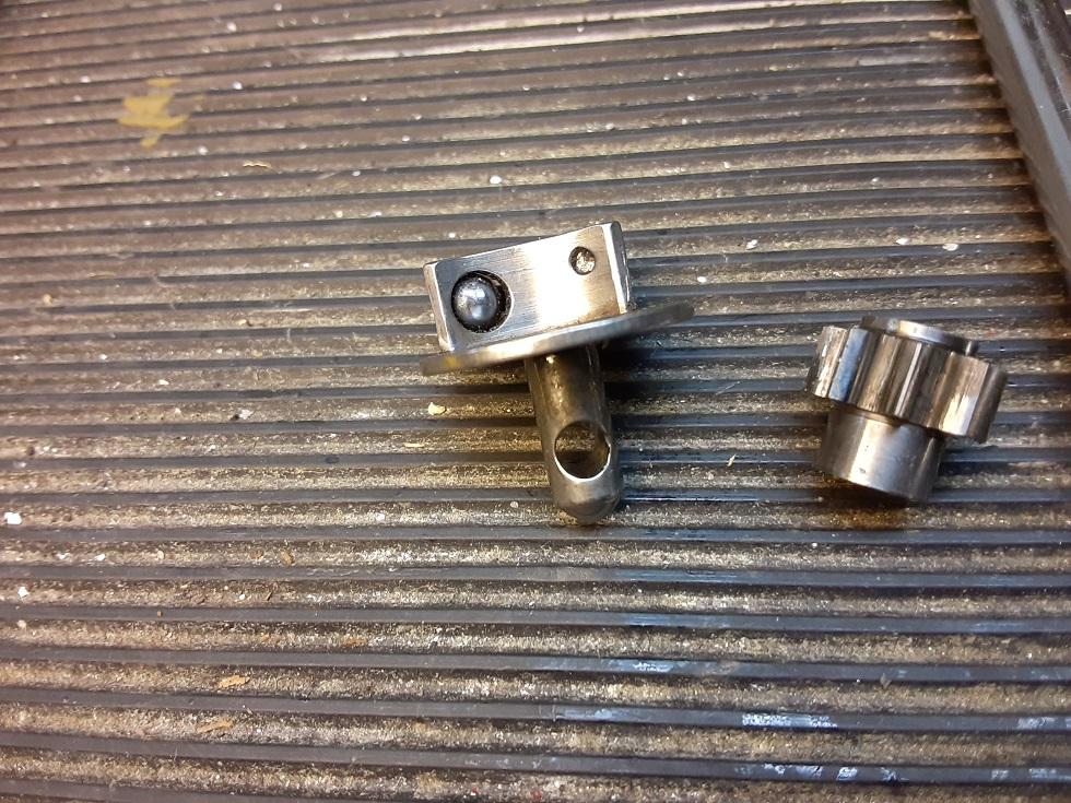
The Pinion screw goes thru the Driving pinion into the shank of the Shuttle Carrier. It is not a set screw. It is more of a threaded pin. I would expect it to be tight. Mine way. This is why it is so important to take the time to fit a screwdriver to this screw, both on a width and thickness basis. You don't want the screwdriver to be too wide and stop on the ID of the Drive Pinion screw hole and make you think it is bottomed in the slot for obvious reasons. Here is the Pinion Screw. My slot was already beat up. Here is the screw on my screwdriver. Note how deep the screwdriver is into the screw slot. It is deep enough that the screw hangs off the end of the screwdriver. This is what you want. Here is my screwdriver inside the screw hole of the Driving Pinion. Note that it passes all the way thru. Again, this is good thing. Here is the Shuttle Carrier. This is the side of the shank where the screw enters from the Driving Pinion. Note that the hole goes all the way thru. Hence my calling it a threaded pin. But also note that on the other side the hole is smaller. Something to keep in mind during reassembly. Getting back to why I took the gearbox apart, the first time I did it, I thought that the fit of the Driving pinion shank to the bore in the gearbox was worn. I wanted to see how much and if I could make a bushing or find another way to restore it. I also thought at the time, that the bore was simply that, a bore directly drilled and reamed into the gearbox itself. Turns out that is not true. There is a steel bushing pressed into the gearbox. This makes it rebuildable by installing a new bushing. However, I measured the shank on the Driving Pinion and the bore of the Pinion Bushing and there is about 0.001" clearance. So, I would think this is fine. 0.0005" might be better. But I'm okay with 0.001"
-
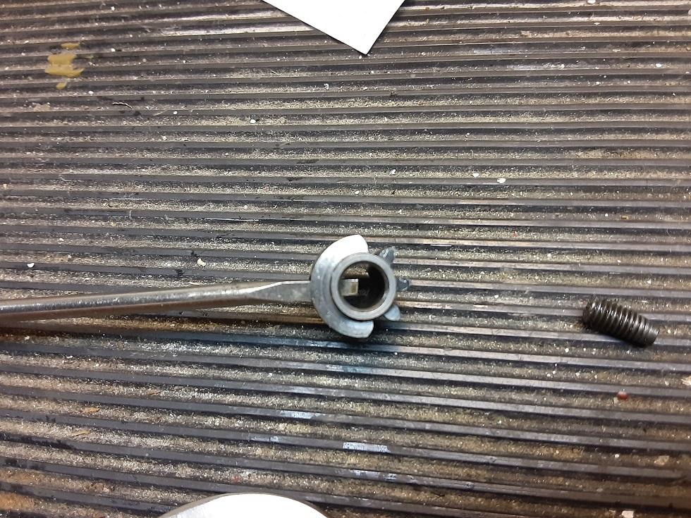
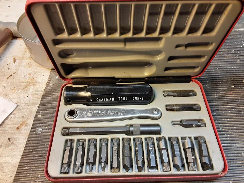
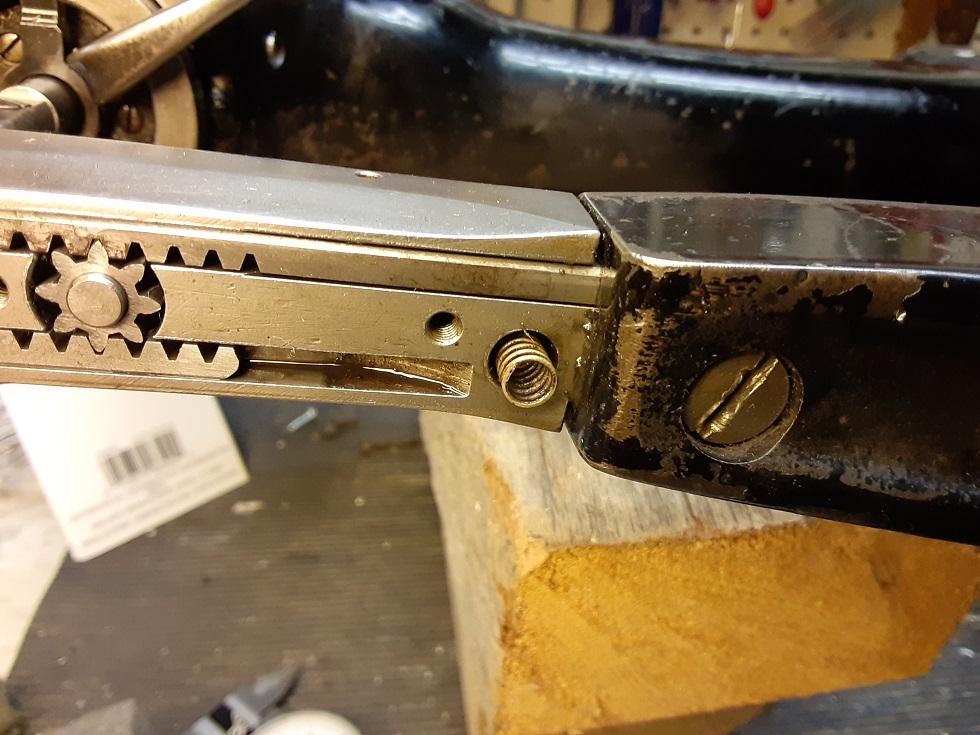
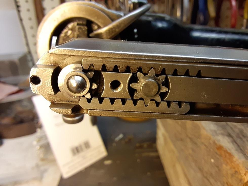
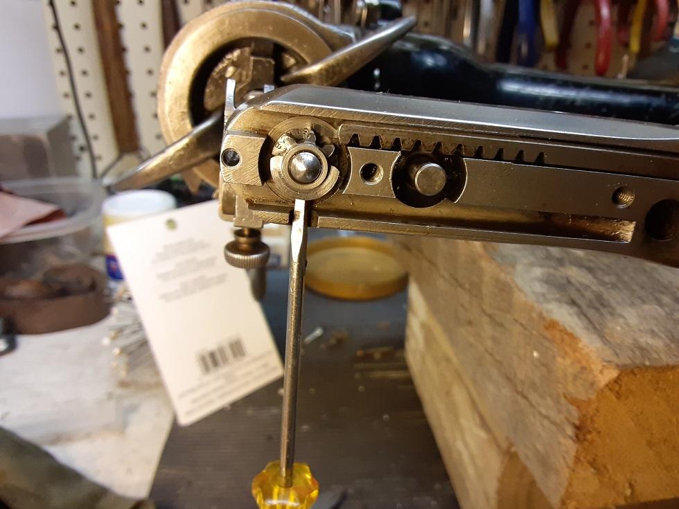
Went back into the gearbox today to revisit what I thought was a worn bore for the drive pinion of the shuttle drive. Figured I'd do another blow by blow for those who have never done this before. First, take the machine off the treadle base if you have one. For stand alone machines just flop it over onto it's back side. Put a piece of wood under the top arm to keep the weight of the foot lift lever. Don't try to go into the gearbox with the machine standing up in the stand because things will fall out or worse, launch out and it is very difficult at best to reassemble the components in that position. Before we get too far, this is a good place to mention good screwdrivers. I also do gun smithing as a hobby and good screwdrivers are a must have to avoid buggering up slotted screws on fine firearms. Here is a set that I would recommend to anyone that works on sewing machines or other fine machinery that uses slotted screws. The tips are all hollow ground which means you can alter them to fit screws, or re-sharpen them if they get damaged. I got these from Brownells. Not the little ratchet wrench handle. Very useful. You'll see that used later. With the machine lying on it's back side, remove the two screws for the cover plate. These have very shallow slots so use a screwdriver that properly fits. Keep figure pressure on the plate as you remove the screws. I suggest you remove the left screw first. Then the right. Keep the plate in place with your fingers because there is a spring behind it. With the screws removed, ease off on the plate and set it aside. This is what you should see. See that spring on the right? That keeps the needleplate locating pin pushed up. This is one of the parts that would try to escape if you had taken the plate off with the machine upright. Remove that spring and then either push out the pin from the other side with an awl or small punch. I use a small magnet to remove it. Here is the gearbox with the plate removed. The two pinion gears and racks may be in a different position. It does not matter. But this is how you will position them when you reassemble the gearbox. First order of business is to remove the lower rack called the Short Rack. It will simply slip out. This is most easily done with a magnet. The remove the Following Pinion, which is the gear on the right. It too just slides off its shaft. Unless you are doing a full strip down, the Long Rack can stay in place. Here is the gearbox with the Short Rack and Follower Pinion removed. The small screwdriver, which has been ground to fit into the slotted Pinion Screw is shown. Note that the Long Rack has been moved to the right a bit by turning the handwheel. This allows you to rotate the Driving Pinion so that the Pinion Screw is aligned with the hole/slot on the back of the gearbox. Make sure your screwdriver fits that little screw. If you destroy the slot with a bad fitting screwdriver, you are in for a lot of mental anguish in getting that screw out. You will see why in the next photos. Continued in next post.
-
Thanks Wiz. I looked all over the web for a chart like that. regards,, Rob
-
I know that thread "size" is really weight thing. I've spent more time than I care to admit searching the web for thread dimensions that do not seem to exist. So, here's my question. I have some unmarked large industrial size spools of thread. I'd like to be able to measure the diameter to get an idea of the actual thread size. Is there a general rule of thumb for doing this. And yes, I've read the thread and needles and the thread sizing trick threads (sounds redundant, doesn't it?) that area pinned above. It's not critical, but I'd like an idea of the grade of thread I have which is unidentified. I have measured thread that is marked and compared it. So I have an idea. But looking for an experienced viewpoint on this. Thanks, Rob
-
Restoring OEM Stitch Length on Singer 29K70
Snakeoil replied to Snakeoil's topic in Leather Sewing Machines
Yikes!!! -
 If I did not see this posted here, I would be willing to argue that those were photos that were photoshopped to look like they were put on another material. I come from a very artistic family. The fact that this is carved, and embossed leather (I do not know what modeling is), I'm blown away by the detail and the realism. I know someone who carves and paints birds from wood. When you see them, you expect them to fly away. Some of his work is in the Smithsonian. I put this work right up there with his. My hat is off to you. regards, Rob
 -
Restoring OEM Stitch Length on Singer 29K70
Snakeoil replied to Snakeoil's topic in Leather Sewing Machines
Yes, all good points, Mike. Regarding m'waves, my SOP is to short out or ground any terminals with a piece of insulated wire before sticking my hands in there. There are some big capacitors in those ovens and if they are charged and you become the short circuit, it can be nasty. -
Restoring OEM Stitch Length on Singer 29K70
Snakeoil replied to Snakeoil's topic in Leather Sewing Machines
Brownie, I have a suggestion for your large industrial spool issue. By coincidence, I addressed this on my machine yesterday. On the base, where that plastic bag is sitting on your machine is where this will go. Find yourself a large magnet or better yet magnetic base. I just happened to find one cleaning out the basement of an estate I'm settling. An old broomstick make a perfect spindle for those spools since they don't turn. Mount about an 8 inch length of broomstick to the magnet or mag base and put right where that plastic bag is on your stand. Run the thread up and over the small spool spindle and on to the oil cup/guide. I was initially going to remove the screw for the side leg on the stand and replace it with a longer stud and a wood spindle screwed onto the stud. But then I remembered I had that extra mag base and it made it much simpler. A tip on finding too magnets is any time you run across a dead microwave over, strip it apart. There will be some really strong magnets inside the magnetron. I have two stuck to a cabinet door in the basement that are about 2-1/2 inches in diameter and very difficult to remove from the metal door. -
Restoring OEM Stitch Length on Singer 29K70
Snakeoil replied to Snakeoil's topic in Leather Sewing Machines
A sheet a paper was used to punch holes and measure the SPI. -
Restoring OEM Stitch Length on Singer 29K70
Snakeoil replied to Snakeoil's topic in Leather Sewing Machines
Actually, I don't have to buy another machine. I've inherited a Model 66 with the nice 7 drawer cabinet. Made in 1913, it belonged to my wife's cousin's Dad who used it to make repairs on things. At some point, her cousin completely restored the cabinet and treadle and made it a decorator piece in his home. Unfortunately, he never put a drop of oil in the machine and it is frozen up, rock solid. Not rusty from what I can see underneath, but only taking it apart will tell. At some point it will come home and I'll dig into it. It has the Red Eye decal pattern and the condition of all those decals is excellent. I have more than my share of winter therapy projects. Yesterday, a friend at the club handed me a vintage Bausch & Lomb Balvar target scope with problems. I took it apart when I got home and found that it has several broken parts. I will machine replacement parts today and bring the scope back to life. -
Restoring OEM Stitch Length on Singer 29K70
Snakeoil replied to Snakeoil's topic in Leather Sewing Machines
Yours is prettier than mine. My decals are all gone. Just vestiges are visible. A rebuilder had spray painted the entire machine with junk paint 40 years ago and that came off with mineral spirits and sometimes acetone to reveal the original Japaning coating from the factory. I see you have the table for yours. I got one with mine too. Very handy accessory. Because mine has a tower extension so you can stand while working, I had to make a new leg for my table. The original leg was split, half was missing and someone screwed an absolutely fugly piece of old house siding to it as an extension leg. I have another tip for you. That big spool of thread you have on the machine does not belong there. That kind of spool is intended to have the thread taken off from above while the spool remains stationary. It is not meant to be pulled off and the spool rotate while on a pin. If that is how all your thread is packaged, you should make a stand to go on the back of your machine with a guide above the spool thru which the thread runs and then goes down to the machine. The guy that had mine did not use the treadle, so he put that type of spool on the back end of the stand where the belt comes thru and ran the thread up to the spool pin and on to the first guide/oil cup. You have what looks like a cup or spool in a plastic bag sitting in that very spot. Rob -
Restoring OEM Stitch Length on Singer 29K70
Snakeoil replied to Snakeoil's topic in Leather Sewing Machines
Even though I said I was going to leave it alone for now, I still might pull the head off again and machine a new roller that will fit the cam perfectly in case there is some wear on the cam. I'm glad to hear that others are finding this thread useful. There is no better way to learn how a machine works than to tear it apart and understand each bit and how they interrelate. Here's another tip. Find yourself a small rare-earth magnet and put on the stand of the machine. The one I use came out of an old dead computer hard drive. These magnets are very strong. When I put a screwdriver, needle, bobbin, shuttle or whatever on the stand, the magnet stops it from rolling away or vibrating off the stand while sewing. -
Restoring OEM Stitch Length on Singer 29K70
Snakeoil replied to Snakeoil's topic in Leather Sewing Machines
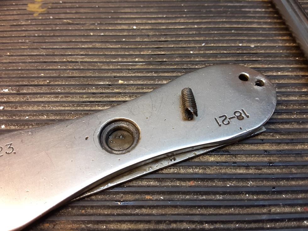
Following up where I left off, today I made a new gib for the Stitch Length Indicator clamp. I had measured 0.030 of Foot bar movement due to wear in the existing components. A spare Indicator came with the machine. No SIMANCO markings or numbers, but identical and virtually new. So the new gib was all I needed. Here is the new gib along with the original Singer gib. Note that the wear on the original gib is at the top and bottom edges. I'm thinking that the gib was not truly worn very much. I'm now suspecting that the wear was in the Foot Bar where it contacts the Gib and Indicator. But I made the new gib anyway and this tightened up the Foot Bar to near zero play fore and aft, which still allowing free movement. Note that on my new homemade gib, the relief cut for the Foot Bar is minimal. I ran a few test stitches down a sheet of paper. I got just under 6 SPI. Might call it 5.9 or 5.8 SPI. That was less than I had expected with the elimination of the Foot Bar play. I was expecting about 5.4 SPI. So, I took the foot off and put a dial indicator on the Foot Bar and measured the movement now that all the play was removed. I set the Indicator at 5 SPI. The Foot Bar moved 0.185" with good repeatability. That length equates to 5.4 SPI, which is what I was expecting. So, my guess is this could be a bit of slippage due to the foot teeth being worn and slipping a bit. I'm probably going to leave it as it is for now. I might buy a new foot and maybe a new roller or two for the head internals. But rather than beat this stitch length horse any further, I'll address the wear in the Carrier Drive Pinion first and try to restore that back to zero play. regards, Rob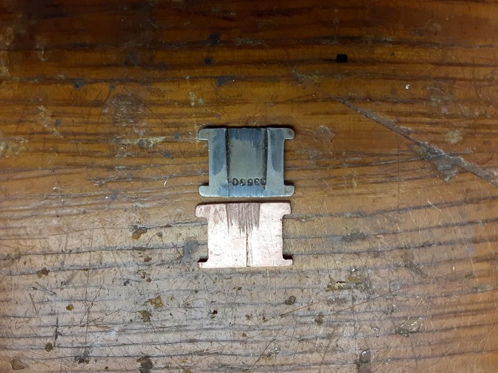
-
Restoring OEM Stitch Length on Singer 29K70
Snakeoil replied to Snakeoil's topic in Leather Sewing Machines
Thanks Constabulary. That's good input. I figured there was a spec for setting this hidden somewhere. But Heaven knows where. I will check my settings and compare to yours. I tend to use the K71 Parts Diagram because it is more logically laid out and the parts list is so much simpler to use. But I've found several "improvements" on the K71 that don't appear on the K70 machine. I think I'm just going to make a new gib for the stitch regulator and sew what I gain in stitch length. But you are right, changing the rollers might gain me a bit more as well. It is amazing how much quieter the machine runs after going thru the head. I suspect the play in the bell crank tongue was one of the "clicks" I heard before and which has now become silent.
