

Snakeoil
-
Posts
82 -
Joined
-
Last visited
Content Type
Profiles
Forums
Events
Blogs
Gallery
Store
Everything posted by Snakeoil
-
Restoring OEM Stitch Length on Singer 29K70
Snakeoil replied to Snakeoil's topic in Leather Sewing Machines
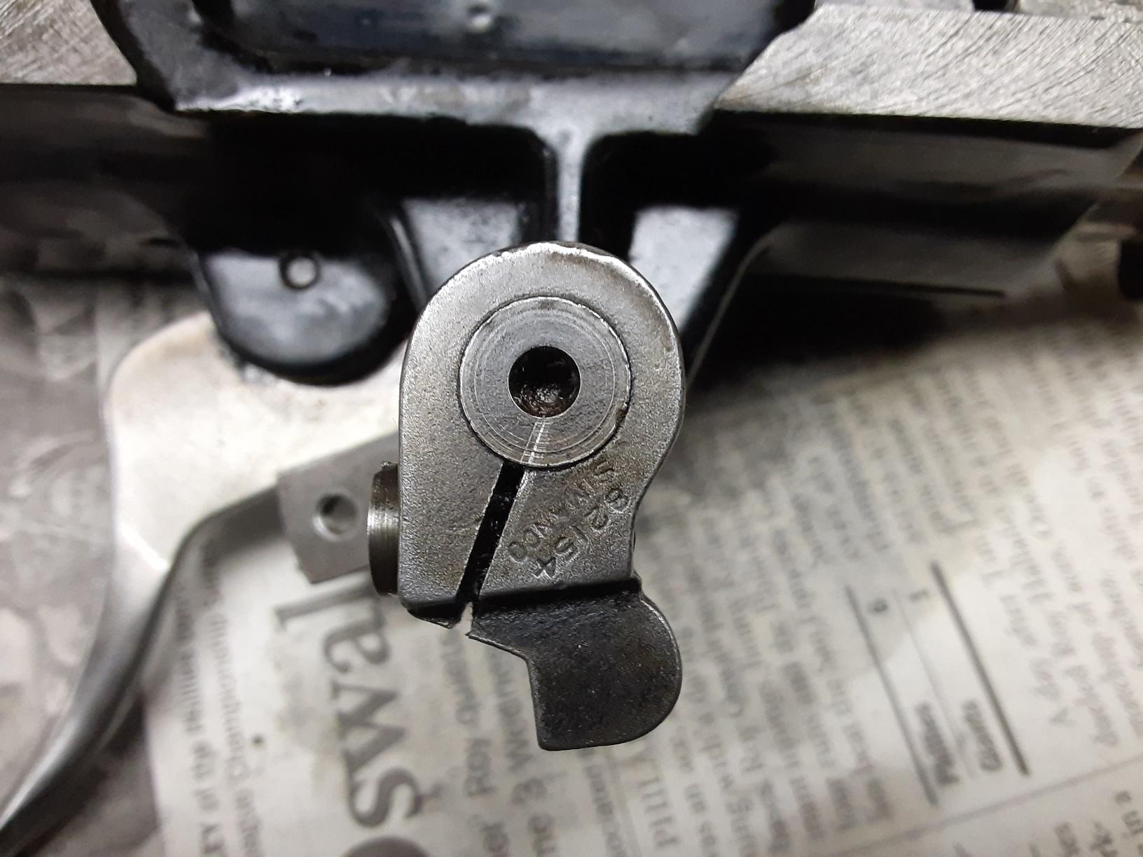
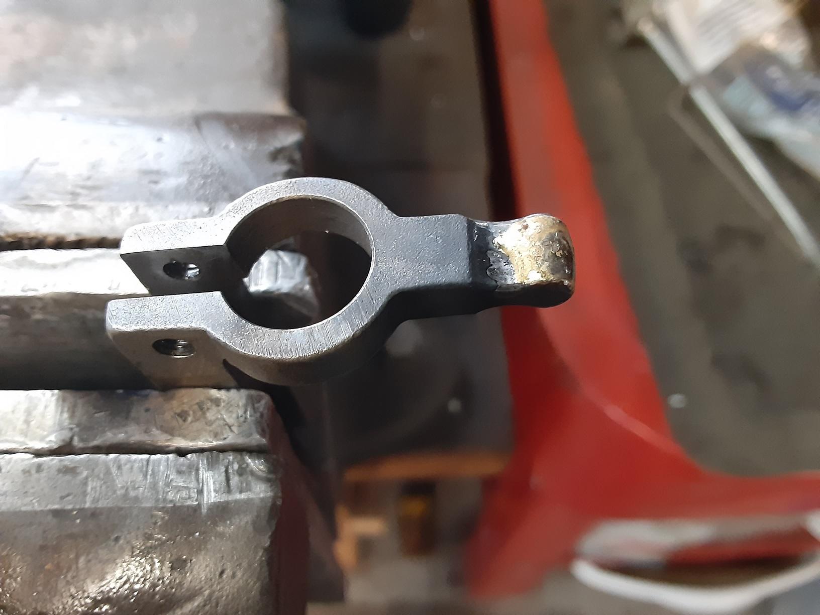
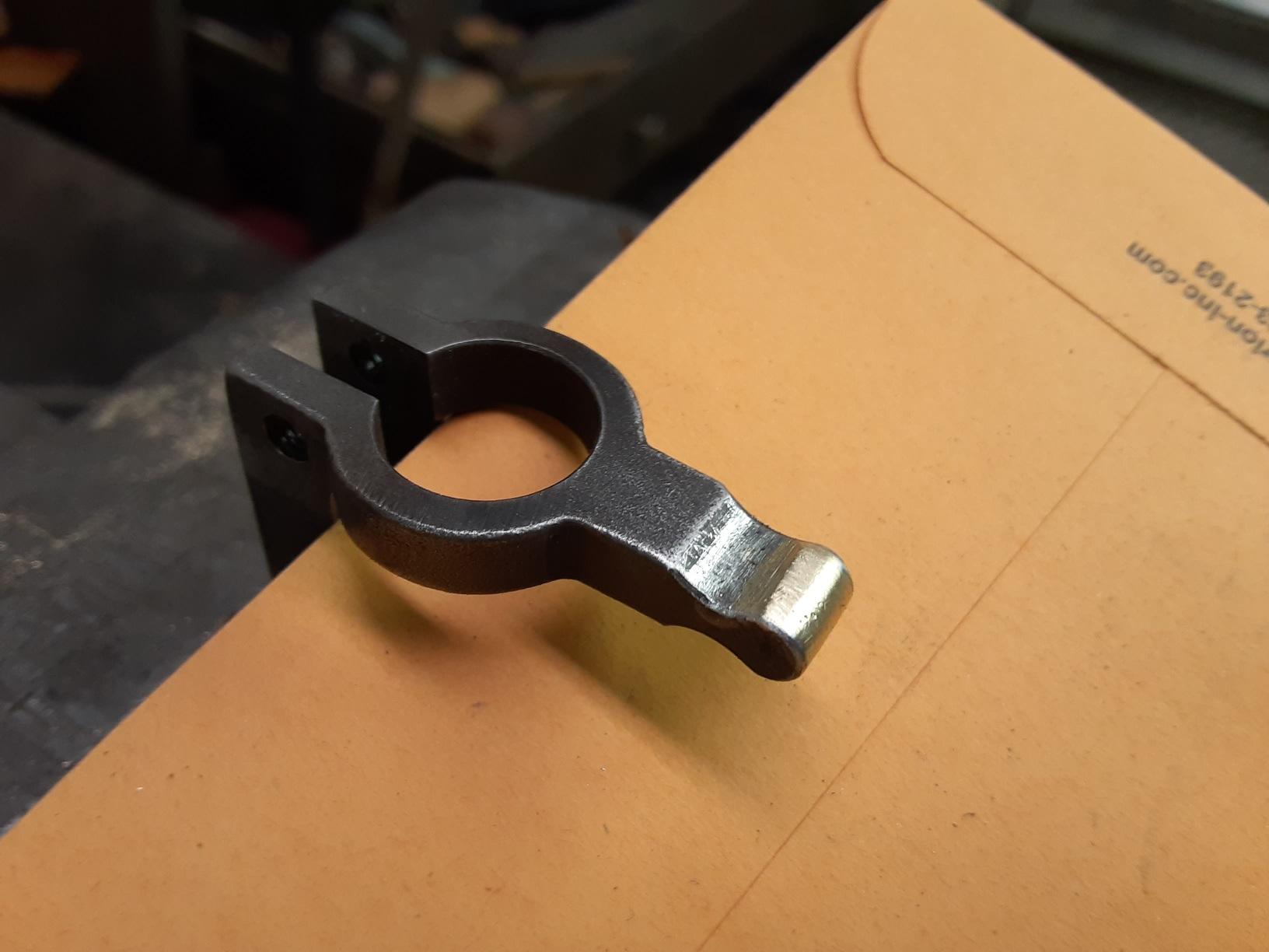
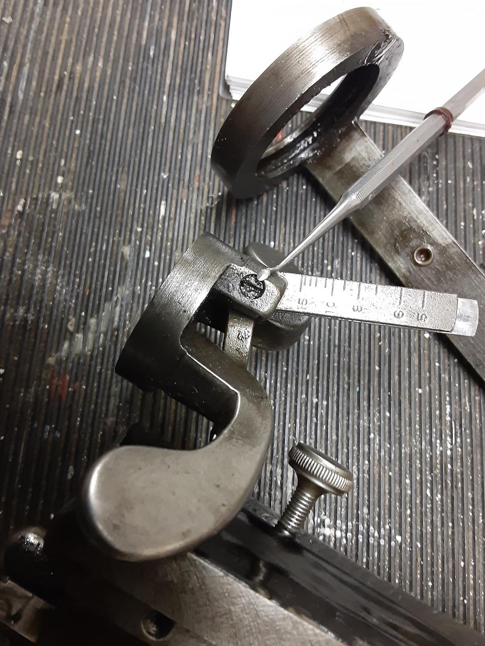
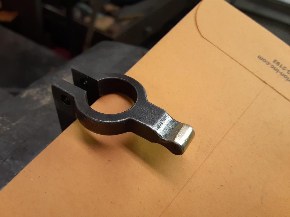
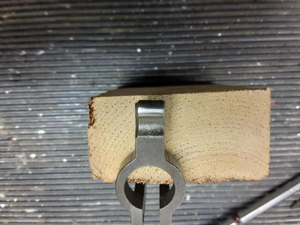
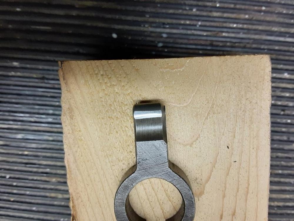
Before you and finish stripping the head, you have to remove the Foot Bar from the Foot Bar Revolving Joint Bearing. This is done by driving out the 1/16 pin at the top end of the Foot Bar. Here's a photo of that pin. The foot bar is not hardened and will bend. This pin is a bit of challenge to remove. You might bend the foot bar. Check it. If bent, carefully straighten and check with a straight edge. The dental pick is pointing to the pin in the photo below. Another spot that made me a bit nervous was the Lifting Lever Shaft Lever, which is clamped to the Lifter Lever. I'm sure there is a procedure for setting the position of this lever. But since my machine sewed fine, I decided to scribe a line with a carbide scribe so I could reposition it where it was during reassembly. Here is how it looked with the line scribed in line with the split in the lever. With that done, I stripped the head the rest of the way down. I cleaned and inspected parts in prep for reassembly. The topic for this post was restoring the OEM stitch length so that is where I will now go. With wear on both sides of the Bell Crank Lever tonque, I chose to braze one side only. Reason being is the steel will wear slower than the brass and if the tonque only wore 0.007" in 40 years of service in a shoe repair shop, Having brass on one side and steel on the other should last longer than me. Here is the tongue with the braze applied. I then dressed down the braze material with small files and crocus clothe until I achieved the 5mm OEM spec. I used the slide bar ring as a gauge, checking my progress. When I got to 0.197", which is 5mm, the tongue was a nice fit into the ring groove. Here's the finished tongue. And that's not a flat spot. That's the light giving that impression. This is another good place for a minor tangent. I read in a thread here that someone wondered if the Bell Crank they had was bent or if some of Bell Cranks Lever Legs are not made at 90 degrees to each other. I checked mine and the legs are set at 92 degrees. So don't think yours is bent if it is not square and you own a 29K70. I put the head back together and mounted it to the machine, oiling everything with Break Free along the way. I did not mention this, but I did find some very hardened crud inside the head. Some of the crud had to be chipped away with dental instruments. But there was no appreciable wear seen anywhere inside the head, other than a slight groove made by the thread in the needle bar and the wear shown on the Bell Crank Lever. With the machine back together, I ran a sheet of paper thru it with the stitch regulator set at 5 SPI and I got 6.5 SPI. I did it several times and each time got 6.5 SPI. That is a slight improvement over the 8 SPI I was getting before. But, I was not content. I wanted to know where the rest of the missing stitch length was going. Having had the head apart, I have a pretty good idea. I measured the moving of the sliding bar ring with a dial indicator. The ring moves vertically 0.139" with repeatability. If I take my Bell Crank leg ratio and multiply it by the ring movement, I get a stitch length of 0.291". A 5 SPI stitch should measure 0.200". So, Singer obviously accounted for the required operational clearance in the machine. But with my bell crank restored to a nice tight fit, where is my stitch length going. I'm pretty sure it is the play in the foot bar at the Stitch Regulator Gib. I measured the amount of free play in the Foot Bar and got 0.030". If you take a 0.200" stitch (5 SPI) and take 0.030" out of it you have a 0.170" stitch length. That equates to just under 6 SPI. But I'm getting 6.5 to 7. So, there is wear elsewhere and could be in the Motion Wheel Cam, the mating roller or both. So, If I either buy a new Stitch Regulator and Gib or fix mine so have near zero foot bar movement fore and aft, I'll gain 0.030 in stitch length. Using my 6.5 SPI that I measured after restoring my Bell Crank, that would result in my getting about 5.4 SPI with my machine, max case. It will reduce as the material being sewn, thickens. I hope somebody finds this helpful. I learned a lot about how the machine works today. Hope this helps pay back the help I've received here since first getting this machine a month or so ago. regards, Rob

-
Restoring OEM Stitch Length on Singer 29K70
Snakeoil replied to Snakeoil's topic in Leather Sewing Machines
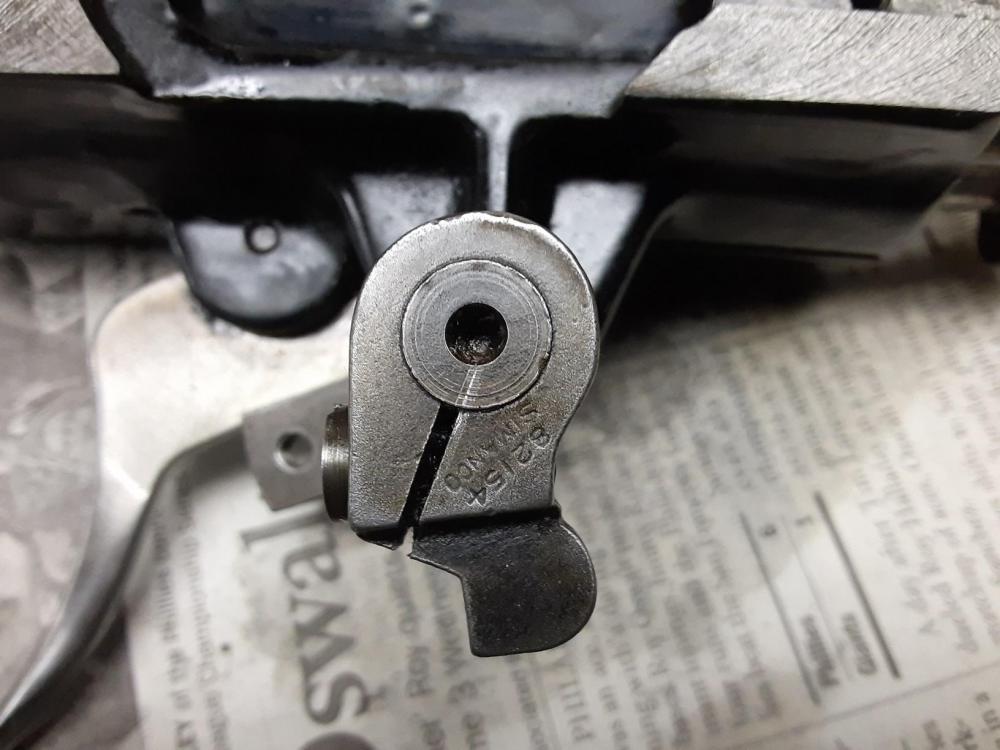
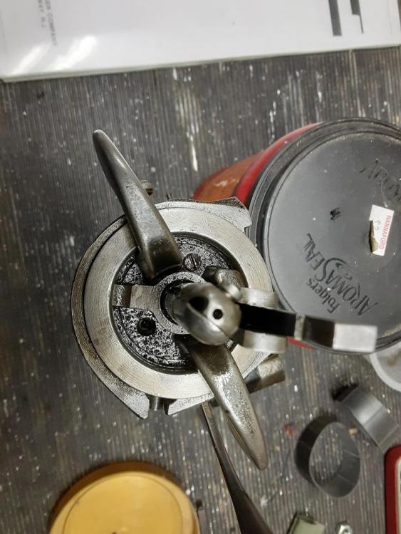
With Bell Crank accessible, remove the two Screw Studs (I cannot find these called out on the 29K70 parts diagram so I'll provide a photo. They are basically the pivot shafts for the Bell Crank Lever that hold it in the Handle. Here is what those screws look like once removed. Screw driver slot is on the right end. With the Bell Crank Lever removed, Here is what I found for wear. Top side of tongue. Bottom Side of tongue According to Constabulary, the spec for the thickness of the tongue when new is 5mm or 0.197". This tongue measured 0.1895" or 4.82mm. So, my tongue was 0.0075 worn. I confirmed this by inserting the tongue into the ring on the sliding bar and was able to get a 0.007" feeler gauge in there with some drag. This is a good place to discuss what the theoretical max stitch length of this machine would be given the dimensions for the existing bell crank lever. I measured both legs of the bell crank. The short leg, which is the tongue measured 1.312" from the center of the pivot hole to the center of the wear spot on the tongue. The long leg measured 2.035 from the center of the same hole to the bottom of the leg. With the bell crank in the machine and the foot down, the distance from the bottom of the long leg of the bell crank to the bottom of the foot was 0.710". So the effective long leg length was 2.745". Basically, a 2-3/4" leg. If we do the arithmetic, the ratio for the Bell Crank is 2.745/1.312 = 2.09. So, for every thousandth of an inch the tongue moves due to the motion of the sliding bar, the foot moves 0.00209 inch. So, for what I was finding with my machine, for the stitch when set at 5 SPI and getting 8 SPI, my tongue would have had to have been worn 0.036". And we know that it wasn't. So there is more in play here. Let's get back to the head in the next post.

-
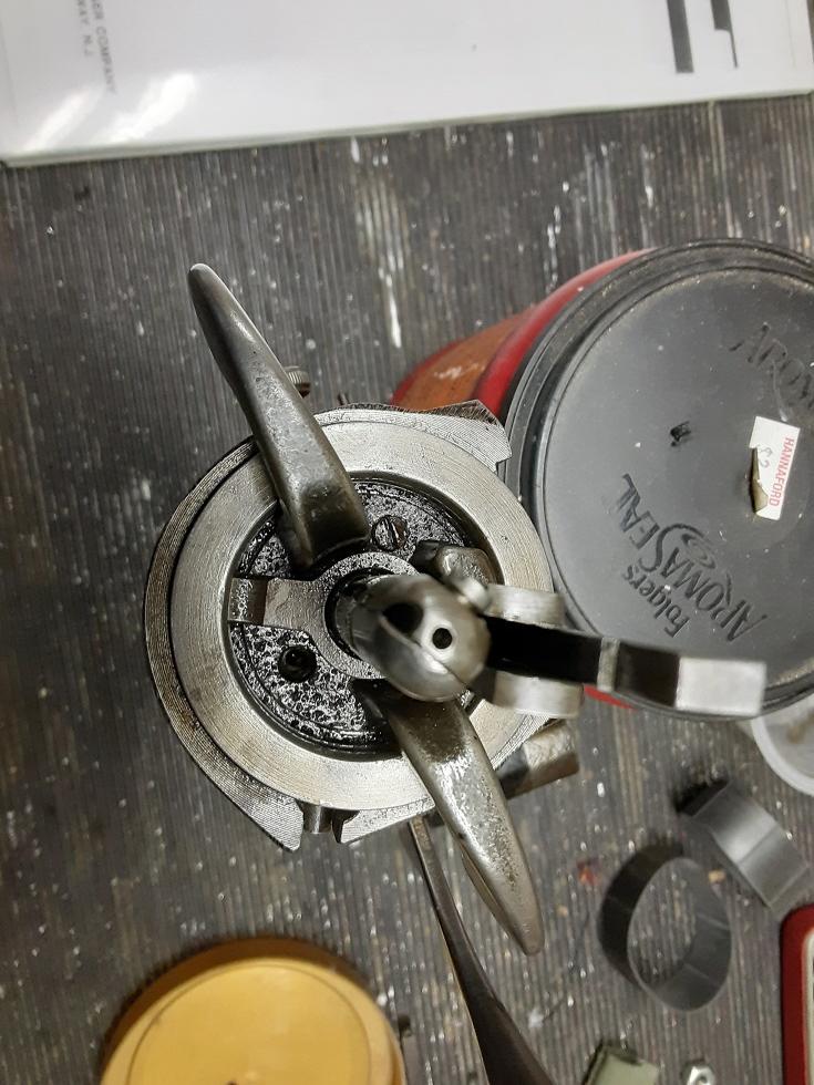
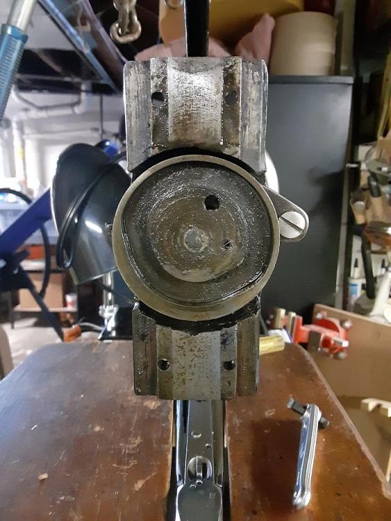
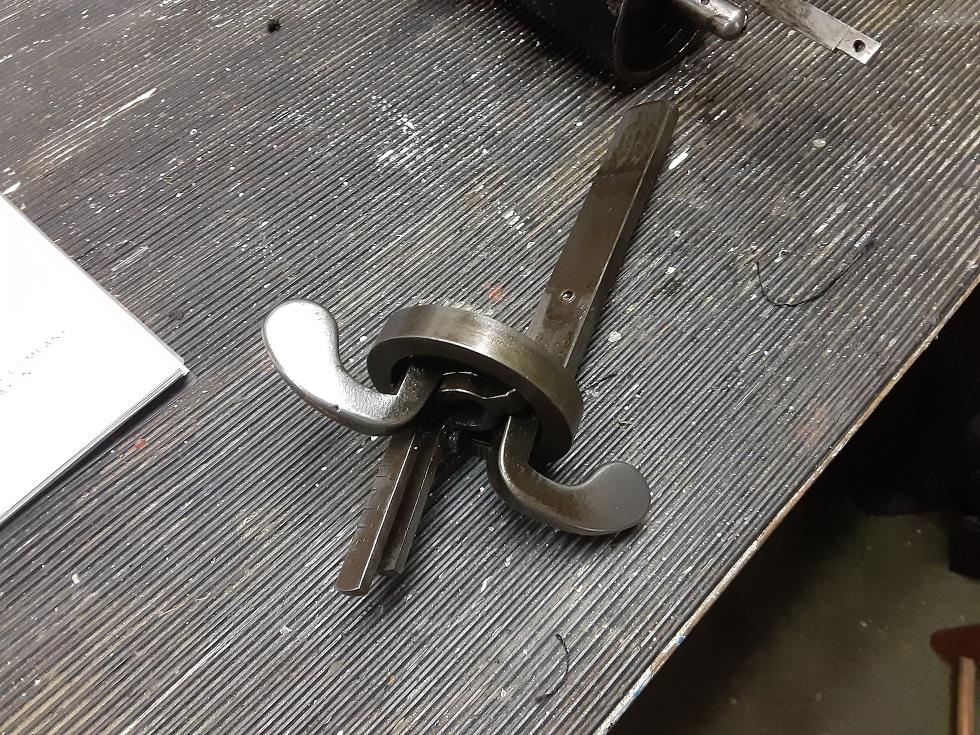
I decided to pull the head on my 29K70 to inspect, clean, and restore the stitch length if possible. I've learned here that wear on the tip of the bell crank is the most common cause for reduced stitch length. First, off with the head. Four screws on the wheel side of the head mounting face is what keeps the head mounted to the top arm. Before removing the head, drive out the pin that connects the piston to the needle bar. Remove the four screws and the head should come off. If it is stuck wiggle it a bit or give a tap with a dead blow or rawhide mallet to free up whatever gum is holding it in place. Here is the head end of the machine with the head removed. A little cruddy, but not too bad. My head needed a wiggle to get off, by the way. The large round disc with the cam groove in it is the Feed Motion Cam Wheel. Here is the inside surface of the head, as it came off my machine. See that little roller to the right of the head on the bench. That roller rides in the Feed Motion Cam Wheel and mounts on that pin at the bottom of the crud patch on the Slide Bar. At this point, remove the foot and the Stitch Regulator (clamp). You can also pull the needle bar out in either direction. Next is removing the Revolving Bush Handle along with the bell crank. Two screws hold the Handle to the Revolving Bush. In the photo below, one screw is already removed. The other screw is at about 1 o'clock in the photo. Here is the Handle with Bell Crank Lever still attached. Continued in next post due to attachment size limitations.

-
Probably should have made the previous post a separate thread. Oh well... Took the cover plate off gear box. Nothing stood out other than the drive pinion for the shuttle carrier was kind of loose in the gear box bore. I see that on the K71 they modified the design to use a replaceable bushing for the drive pinion bearing. But on the K70, the gearbox is simply bored and the pinion runs in that bore. I did find that carrier slop I reported in the previous post is due to a combination of lash between the gear and racks and excessive play for the drive pinion. I was pressed for time so did not take measurements. I'm hoping the drive gear is the wearing component and replacing that will reduce if not eliminate the play. Another option is to simply machine a thin bushing to take up the clearance. Will revisit this. With the shuttle drive out, I found it was packed with oily paste from years of use. The carrier spring had signs of wear as well. I have two spares that came with the machine. When I go back into the box to take measurements and see what can be done to tighten things up, I'll probably replace that spring. I have two needle plates that do not fit this machine. Once has the counterbores for bobbin clearance and the other does not. Both are identical with respect to hole placement and that placement is different than on my K70. The bobbin clearance looks like it is for a large bobbin machine. But the parts diagram I have for K72 machines shows a needle plate that looks like the ones on my K70. Maybe these are from an earlier or later design large bobbin machine. I'd be willing to trade these for K70 parts. They are not unused, but damn close to it.
-
Thanks. Amazing how much Singer stuff is on ebay.
-
I have another issue with this machine. Two actually, but they may be related. I checked the timing on the machine today and it is a little late. By that I mean the edge of the shuttle carrier is not covering the first third of the needle hole as described in the manual. In adjusting it, I found that there is quite a bit of rotational play in the needle carrier. I'm thinking that either the drive pinion is worn or the screw that holds the carrier to the pinion is loose. I'll be looking into that issue. What may be a related issue is when I use a different shuttle than the previous owner used, the machine sews well until the thread for some reason gets wrapped under the shuttle carrier. I have to remove the needle plate to be able to move it out of the way and cut the thread. With that done, I use tweezers to pull the thread chunk out from under the carrier. It only seems to happen with that shuttle. I like that shuttle better because the tension spring is perfect. The other shuttle has a spring with a razor edge where you work the thread under the spring and it is easy to cut the thread in the process. I compared the shuttles and the appear to be identical and with no difference in wear. I moved my light to the rear, Constabulary. I needed to get at that hole to adjust the timing and figured I might as well move the light while I had it off. Thanks, Rob
-
Thanks Wiz. Purely by coincidence, I happened to be reading the specs at the front of the 29K71,72,73 machine from the Shoe Systems Plus website. It appears that this is a manual published by Singer. The specs for those machines, which I would expect to be the same as the K70 since they use the same bell crank, shows the stitch length as 7 to 15 SPI. I wonder if Singer decided to move to a more realistic number. regards, Rob
-
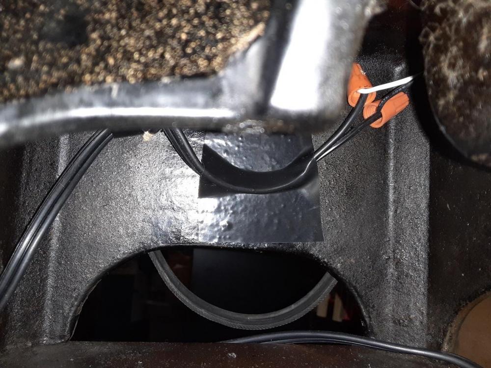
Had not considered the pendulum effect and of course, this is a key variable in the stitch length equation. I'd like to think this would have finally dawned on me if I stared at the machine long enough. Thanks for short circuiting my slow thought process. I discovered another factor that might come in to play from time to time. I took a thicker piece of cardboard and ran it thru the machine. It would feed fine and not feed fine. If I pushed it or pulled it, all was well. But it would stop every so often. What I found was that the needle upset the backside of the cardboard enough that it was apparently getting pushed into the needle hole on the needle plate and in essence, getting a "grip" on the plate. Have not seen that happen with leather or cloth. But some leathers might do this. I made a case the other day for a spotting scope lens from a cardboard tube. The bottom side of the cardboard had felt plus being curved, the area at the needle hole was raised off the plate a bit. But if I were covering a flat cardboard based case with something, I could see this happening. Yeah, I figured that hole was there for a purpose. I also considered mounting the lamp on the back. Every other machine I've seen has the lamp mounted on the back in some fashion. I did not want to drill the base. I hate modifying original equipment. The hole was there, convenient and expedient. I may search the machine for another mounting point. What I like about it on the front is it lets me light the bobbin winding process. I have the machine squirreled away in a spot in the basement. I probably should just put an LED shop lamp over the machine and brighten up the entire area.
-
I imagine one of the parts vendors may have one of these. But I thought I'd ask here. Does anyone happen to have an oval Singer Badge/Medallion they'd be willing to part with. The Badge on my 29K70 is missing and it bugs me. The 29K70 model plate is there, but no badge. Would not mind finding a set of replacement decals either. But they are secondary to the badge. Thanks, Rob
-
Thanks for the kind words. Funny you should mention that. The other day, I took a plain piece of white paper and ran it thru the machine with no thread. It punched a nice row of holes damn near 5 SPI. Yet when I sew anything thicker than a sheet of paper, which is just about anything, best I can do is about 8 SPI. So, I'm wondering if part of the problem is slippage of the foot. I did sharpen the teeth on the foot with a small triangular stone. But then again, I suppose it could be that the paper offered zero resistance to moving and hence made it easier for a worn bell crank to produce 5 SPI. I think I might pull the head off the machine tomorrow and get a closer look. Peering up into the bell crank area I see it swings on two screws. Play in those would also contribute to loss of stitch length. I'm sure a redesign could produce a bell crank arrangement that would not wear. But it would require a major redesign to eliminate the rubbing surfaces of the crank and the ring and replace it with an adjustable pivot point similar to how the foot lift is adjusted. I have a new Husqvarna machine that I bought for my wife and I'm the only one who has ever used it. I'm suddenly curious in how the stitch length is changed. It's under my desk. May just have to take a peak tomorrow. But I don't see me reinventing the 29K machines in the near future. After all, if it ain't broke... regards, Rob
-
Figured out the thread size for the side tensioner. Once again, the Singer education process plays a role. I'd thought it was a #10 screw with a different pitch thread. I estimated it to be a 36 thread. Too small ID to get a pitch gage on the thread. So, I cut a 10-36 test screw on the lathe and too big. Dropped it down to a 8-36 and too small. The 8-36 threaded in loosely, but stripped. I was thinking that somebody stripped the threads in the head and that's why the tensioner was missing. Then I found that the thread for the Check lever spring tension stud was 9/64-36. Hmmm, if they used a unique size there, they could have used them anywhere. The story is longer, but I'm probably putting you to sleep by now. I ended up turning a piece of wooden dowel to 11/64" and then forced it to thread into the tapped hole. Bingo. Gave me a nice impression of the thread. Put my pitch gage on it and it turned out to be 40 tpi. So, it looked like it was an 11/64"-40 thread. I checked that against the photo Evo160K posted of his Singer tap set and dang if there is not a 11/64"-40 tap in that set. Thanks again for posting that Evo Turned an 11/64"-40 test screw on the lathe and fit like a glove. Went thru my Machinery Handbook looking for that thread size. Nope. There are no thread sizes in 64ths listed in any size. This apparently was a Singer proprietary screw, like most of the other screws on the machine. regards, Rob
-
Evo,
Can you please confirm the thread sizes printed on that package of Singer taps? I cannot with 100% confidence read them all and a few are truly foreign to me. Here is the list I made reading off your photo.
3/32-48
3/32-56
1/8-40
1/8-44
124-50
46-40
9/64-36
9/64-40
5/32-32
82-40
11/64-40
13/64-32
3/16-28
3/16-32
15/64-28
214-32
14-20
¼-24
5/16-18
5/16-24
Thanks,
Rob
aka Snakeoil
-

Rob, unfortunately I don't have the full kit with the plastic package, just the four taps that Shoepatcher recommended to be the most useful for him... 15/64-28, 9/64-40, 3/18-28, and 11/64-40. If memory serves, they were about $20 each delivered. Those four taps have taken care of everything I've needed so far to refurbish a 45K25, a 45K53 and a 45K69.
In looking at a photocopy of the tap catalog page with sizes that Keystone sent to me to order from, I can say it does show all of the sizes you've list above, with the exception of those I've identified with a double question marks (??). The bottom of that catalog page showed "other taps available", but it didn't print clear enough to read. You might want to have them email the list of Singer taps they have available.
3/32-48
3/32-56
1/8-40
1/8-44
124-50 ??
46-40 ??
9/64-36
9/64-40
5/32-32
82-40 ??
11/64-40
13/64-32 ??
3/16-28
3/16-32
15/64-28
214-32 ??
14-20 ??
¼-24
5/16-18
5/16-24
Beautiful, beautiful work you did.
Al
-
Thanks Al, for the response and the kind words. Those crazy numbered threads are something I've never seen before. I suspect that 14-20 is 1/4-20 which as you probably know is a standard UNF threadform. But the others which are just a number and a pitch are a total mystery to me. I may give that outfit a call and see what they are willing to do.
Thanks and regards,
Rob
-
-
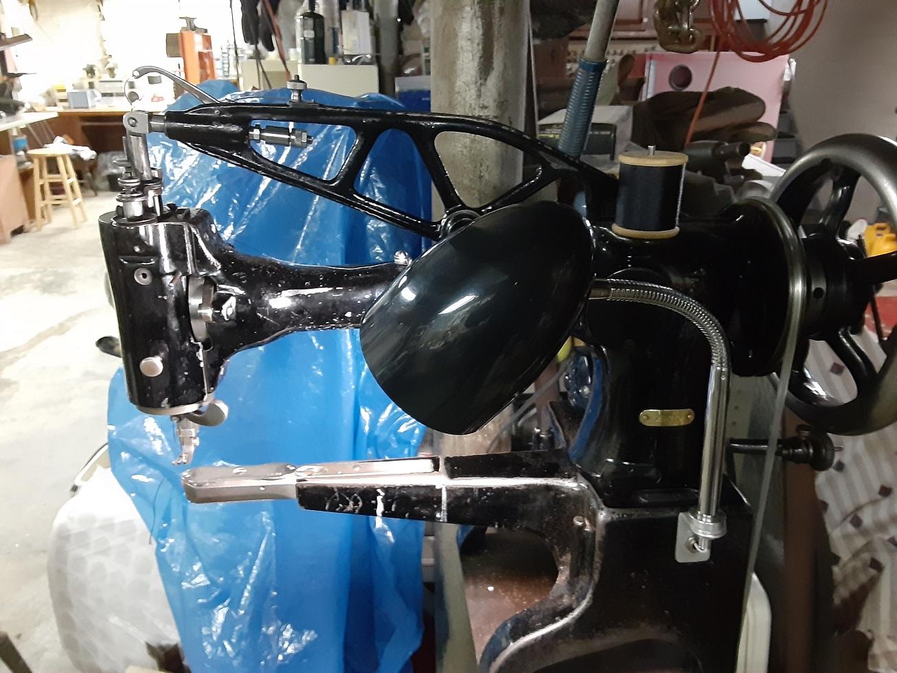
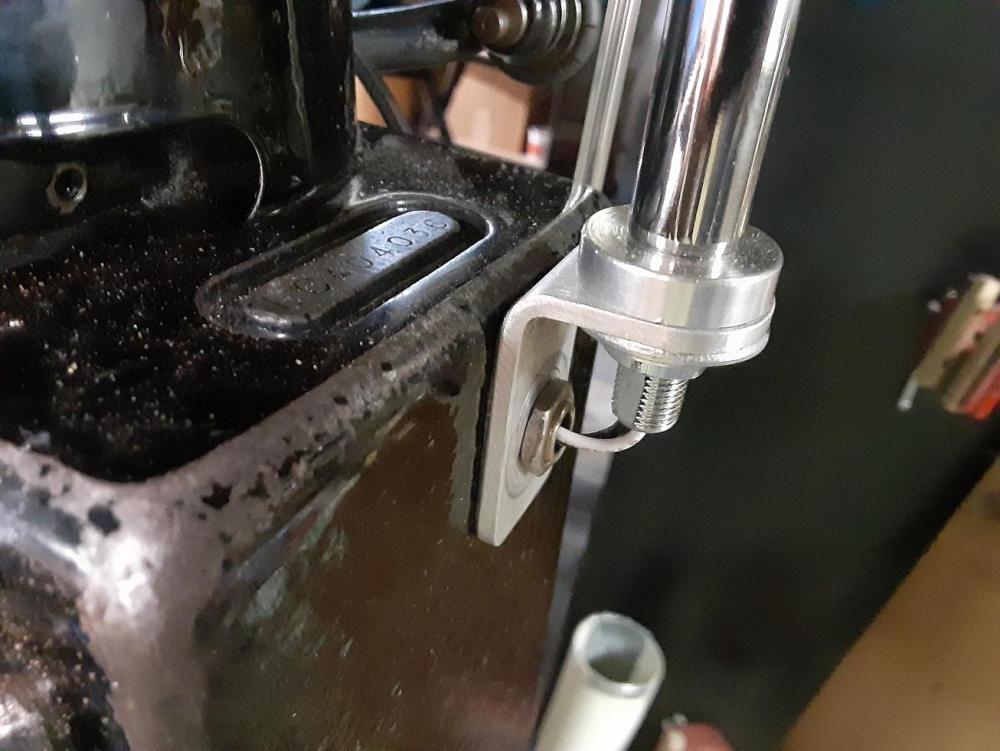
Thought I'd share my light mount. I thought about mounting a tubular light in the OEM position. But then I remembered that Walmart sells these great LED desk lamps for about $6. I have one on my bench grinder. So I picked up another one and found a place to mount it on the machine. The base has a 1/2" hole drilled into it. It appears all the 29K machines have this hole. Suspect it is for accessing a bolt or screw under the base. First job was removing the base from the lamp. Pretty easy. Also uncrimped the cheap, Made in China by prisoners, crimped connectors to disconnect the lead and switch from the lamp. I did not use the switch. The light simply comes on when I plug in the lead. I don't leave it plugged in when not in use. Using a piece of threaded lamp tubing , a few nuts, and a small right angle bracket I had in my odd metal box from a previous Go-Pro mount project, I mounted the light to that existing hole. I also had the aluminum spacer. But a stack of washers will work as well. Goosneck allows you to point the lamp to light whatever area you are working on, an of course to light up the needle area when sewing. Here is a close-up of the bracket mount. Used the original lead from the lamp, simply removed the base and switch. Terminated the lead to the lamp under the base and then taped the wire to the side of the base to avoid it rubbing on the shuttle driving lever and connecting shaft.

-
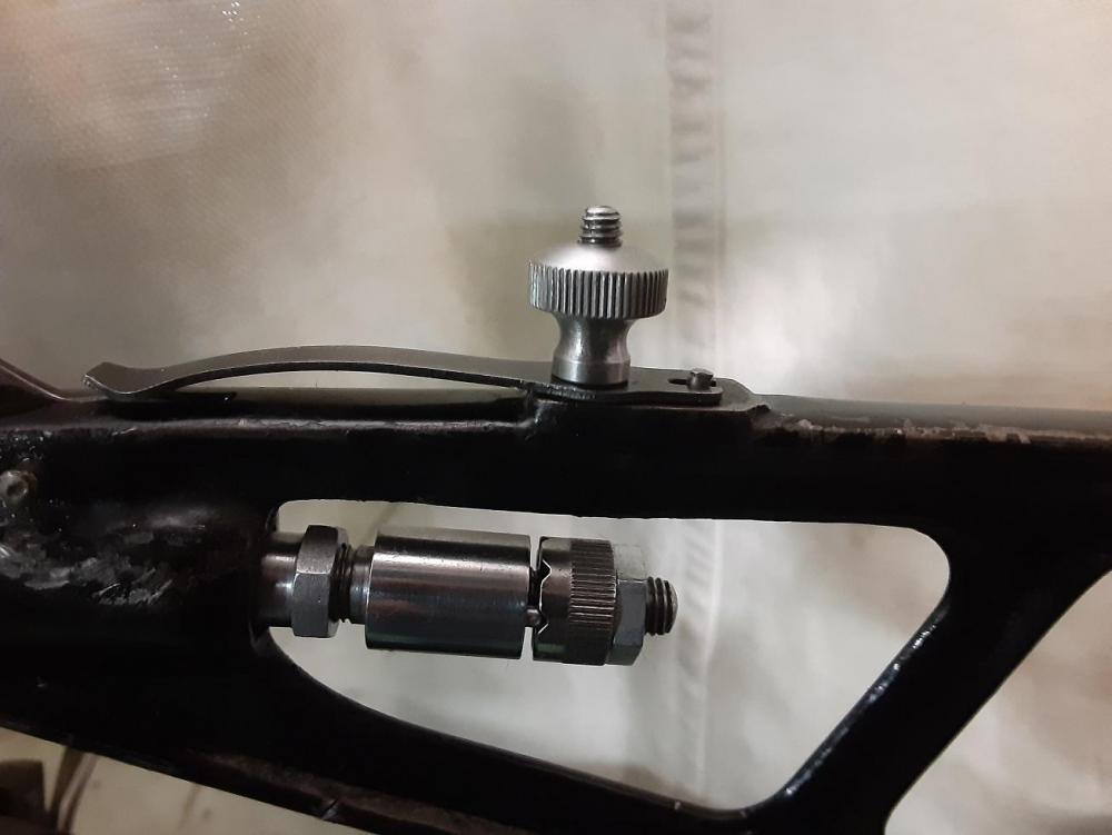
Finished the Check lever spring adjuster and stud. Here is the spring adjustor and the Check Lever Thread Take-up Adjuster installed on the machine. regards, Rob
-
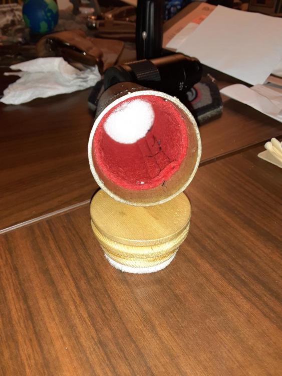
Now, I'm a newbie so many of you may roll your eyes when you read this because it's common knowledge. But it sure wasn't for me. I made a case for a zoom eyepiece that goes to a Kowa spotting scope. Very expensive piece of equipment. I was making adapters to use a webcam on the scope and needed both eyepieces to fit the adapters. It's my shooting partner's scope and he gives me the zoom eyepiece in this POS old cardboard box with tape around it and no flap on one end. There was no way I could give that back to him in that crummy box. So, I decided to make the case. Used a 2" shipping tube. Lined it with red felt. Turned cedar end plug and cedar cap plug, both with foam pads and gave the cardboard tube a couple coats of acrylic poly. Came out decent. The trick came out of frustration. I wanted to sew the felt to the inside of the tube rather than glue it. Sewed up a felt tube, inserted it into the cardboard tube and then stitched it on my 29K70. When I was done, to my dismay, the felt was only tacked in one spot and the rest was all bunched up and shoved down the tube. Ripped all the stiches out and tried again, trying to see if all was going well. I thought it was but was wrong. Nice thing about the Singer is it will track the first set of needle holes perfectly. Ripped out the stitches again and thought about it. Then I had an extra synapse fire and got an idea. Took a sheet of paper and rolled it up to fit inside the tube. Cut it so it was only one layer when expanded into the tube. Stuck that in the tube and now the felt was between the paper and the inside of the cardboard tube. Stitched it for the 3rd time and success. The paper served as a glide material that would not catch on the arm of the machine. Once done, just had to rip out the paper. Will keep this trick in mind for future projects involving felt or other material that tends to catch easily on things. Here's the case. Nothing fancy. But wanted to show how I stitched the felt to the cardboard. The foot tore up the cardboard a bit. If I wanted this to look pretty, I would have covered it in vinyl. But it's purely utilitarian. I love this machine.

-
Nice set of taps. I would expect specialty taps like this to be available thru any of the major tap and die makers. But they probably would not make just one for you. You'd have to wait until they made a run of a particular size to buy just one or two. The markings on the package just confirmed one of my suspicions. I measured the check lever spring screw thread the other day to make the stud and knurled adjusting nut and it was a tad bigger than an #8 screw. It measured 0.140" OD and a #8 is more like 0.136" OD. I would not expect a screw to be oversize. That's when I looked up at my decimal chart and saw that 0.140" is 9/64. So, I suspected that Singer used their own screw sizes as well as pitches and what I just measured was a 9/64"-40 screw. And now I look at your package of taps and there it sits. Now I understand why the test thread I made for the side thread tensioner stud was too small. I think I made that an 8-40. Will revisit that one soon. Thanks for sharing your tap set. regards, Rob
-
Buying a laser engraver never crossed my mind. I took a look and they are not terribly expensive. I've considered making sights for vintage single shots and the limiting factor was the ability to engrave the windage and elevation markings. Might have to think about this a bit. Thanks for the poke.
-
I'm a newbie with about 3 weeks of experience with these machines, so please keep that in mind. First, I found the file below a few days ago. Might be helpful for future reference. Somebody posted it here several years ago. Regarding that groove in your needle bar. If that is truly wear and the area should be flat, here is an untried suggestion. Get some good epoxy like PC-7 or JB Weld. Thoroughly degrease the area and fill that groove with epoxy. Once cured, dress it down with a fine cut file until you are back to flat and only the groove is filled. Not as tough as steel, but pretty tough stuff. I've used it for pitting fork tubes on old British motorcycles with great success. Also did the hydraulic cylinder rams on an old Cat dozer 30 years ago. They were a pitted mess and they are still leak free today. If you have access to fine steel powder, mix some in with the epoxy and it will have better wear resistance. If you have a good industrial supply house near you, or want to search the web, they make metal filled epoxies for repairs like this. I've used them to repair milling machine tables after somebody had run a cutter into them. I'll be digging into my head next week so that video Jimi posted should be helpful. Thx. regards, Rob Singer29K13 Rebuild.pdf
-
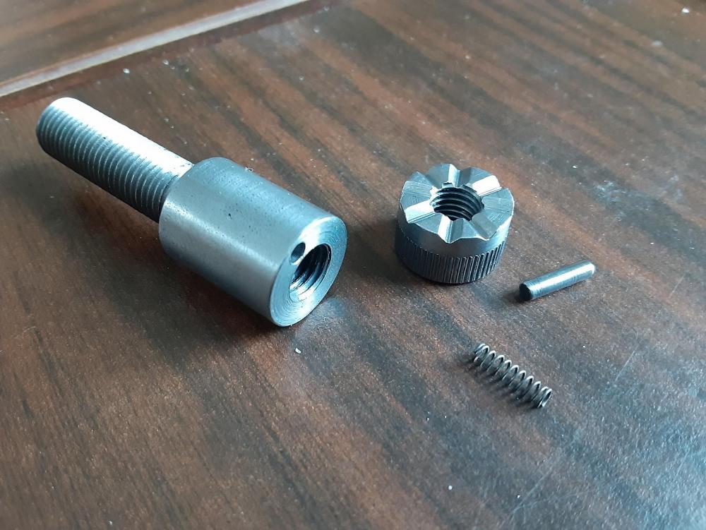
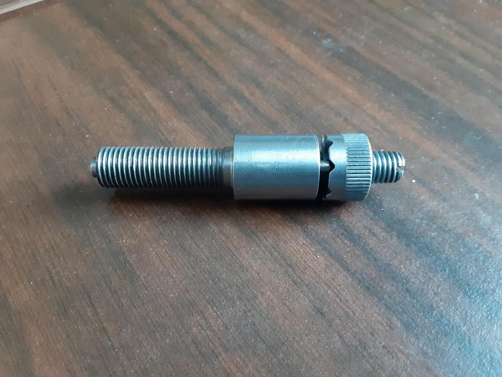
Well knock me down and call me Nancy. I went down to my Dental Cabinet (not mine. Given to me by a friend from his days in dental school) where I keep lots of tiny parts, screws, etc., and found not one, but TWO tiny springs. No idea where they came from or how long I've had them. Both were nearly the same OD. Short one (which I used) was 0.082" and long one was 0.084". Drilled the Indicator Body with a #45 drill (0.089") and machined a plunger to 0.087". Rounded the end and polished. Then case hardened the end and repolished once hard. I still need to harden the Index Head. Although I doubt I'll ever move it enough to cause any measurable wear. I don't have any tiny number stamp so I cannot mark the Index Head. I refuse to do it with a vibro-engraver. Maybe I'll just put hash marks on it. Afterall, if I cannot count up to 8, I probably should not be running machinery. Here are some pics.
-
Thanks for the kind words. The only way to make these parts economically would be on CNC equipment. I'd be more open to making one for someone in trade for similar services or parts. I make custom pieces for fellow shooters, mostly just because they are friends and have shared their experience with me to help me improve. I'm always surprised to have one of them hand me something for one of my rifles without me asking. Jobs like this are my winter therapy. I'm not one to read the paper or sit on the couch and watch the boob tube. Blathering on forums like this (I really only participate in 3) is probably my only vice where I'm not really doing anything "productive". I always try to contribute, even if a newbie to the topic and this post was intended as a contribution, not self-indulgence, Facebook, lookit what I did, kinda thing. Although I have to admit, I'm normally proud of how things turn out so I guess there is a little "lookit what I did" mixed in there. I touch type (thank you high school typing) so I know I can get a bit wordy. But the goal is to be clear. By the way, the damn hex I cut on the indicator body lock nut is not perfect. I tried to take too big a cut in the mill and the piece twisted in the collet. It cleaned up about 95%, but I still can see it and it bugs me. But the machine is not perfect so it kinda fits in. Today, my search begins for the tiny plunger spring I need. If I find one, I should be able to finish the assembly today. Constabulary, can you confirm that the stop pin on the Index Heal only allows for one turn of the head? And do you happen to know the pitch of the adjusting screw thread. I'm not going to change it now, but am curious how close I got. regards, Rob
-
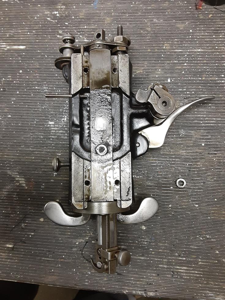
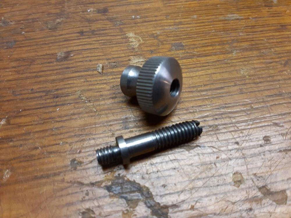
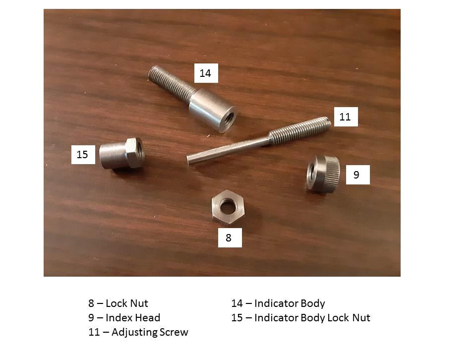
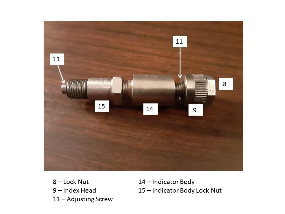
As I mentioned in my first post about me new to me 29K70, the take-up lever adjuster was missing from the end of the piston. Plus, the piston turned out to be for a 29K71 machine. I suspect the change was an upgrade for the K71 as it provided a click adjustable range for the take-up lever where the K70 was a simple screw and lock nut. The actual Singer name for this assembly is Check Lever Thread Take-up Adjusting Screw with Indicator. Nobody seemed to have those parts so with dismal weather outside, went down to the basement to make the parts from scratch. I'm going to do my best to use the terms that Singer uses for these parts. Owning one of these machines is like learning a new language. There are photos below that use the same item numbers as the 29K71 Parts Diagram. The numbers are referenced in the write-up. First order of business was determining the thread pitch for the female thread in the piston. Turns out it is a 5/16-28. No part of the Unified system so no taps in my machinist chest. Used a piece of 1/2" cold rolled steel to make the Indicator Body (14) and single pointed the thread on my lathe and using the piston as a thread gauge. Next was the Locknut for the Indicator Body (15). Locknut was another single point thread operation. But at a minor thread diameter of 1/4" it required one tiny little threading tool. Ground one up and made the nut. Hex for the nut was cut on my little Altas horizontal mill. The Adjusting Screw (11) was made from a 1/4"-28 bolt. I had to cut additional threads on the bolt shank. But being a UNF thread, this was a simple matter of running a die down the shank. With that done, turned the plunger portion of the Adjusting screw to 5/32", which is a size I arbitrarily chose. Left enough wall thickness for the 5/16"-28 Indicator Body thread and was beefy enough for the application, which is adjusting the position of the Take-up Lever. I think I am going to case-harden the end of the adjusting screw where it contacts the Check Lever. Next was the Index Head (9) which was made from another piece of 1/2" cold rolled steel barstock. Knurled one end and then drilled and tapped 1/4"-28 to fit on the Adjusting Screw. Last part was easy, the Lock Nut (8). Just took a standard 1/4"-28 nut and faced it down into a nice thin jam nut. And before somebody pipes up and say that I left some parts out, I know. The tiny spring and plunger that provides a click stop type of adjustment for the Index Head has not been done yet. First order of business will be finding a tiny spring. I'm thinking an old spring from the flint in a cigarette lighter. The stop pin is also missing. I believe the stop pin allows only one revolution and butts up against the plunger in either direction. But my checking of the total travel of my Adjusting Screw relative to the amount of adjustment available for the Check Lever resulted in my set-up having 3 turns of range. So, I will probably not use the stop pin. I also have to cut the V-notches into the Index head for the plunger stop points and put indicator marks on the Index Head. Here is the assembled Check Lever Thread Take-up Adjusting Screw with Indicator. When this is done, next order of business will be restoring the stitch length to full spec. I suspect I'll be removing the head and either brazing or welding up the tab on the bell crank and then hand filing to spec of 5mm diameter. I now understand why this was an upgrade to the later 29K machines. It gives the machine the ability to put a little more positive tug on the thread versus relying on just the spring pressure of the Check Lever Spring. Regards, Rob
-
This is how I started this post over in Leather Sewing Machines: "My max stitch length is about 8 SPI. My understanding from reading here is the bellcrank is normally worn and is the root cause for the reduced stitch length. I was looking at the machine today and it would appear that to replace the bellcrank the head has to come off the top arm first. I see 4 screws that look like they hold it in place. Looking for some guidance here. Have only the parts diagrams as a guide. I also wonder about the gib and clamp that sets the stitch length. There appears to be some play between the foot bar and the bell crank. I would expect their to be some since the foot bar moves relative to the bell crank. But the fore/aft play must contribute to reduction in stitch length. Is play in that gib/stitch regulator clamp relative to the foot bar normal, or do I need to replace the gib and regulator as well?" I took a break and tried searching the site for the answers before posting this. Did not have a lot of luck. But doing some previous Google searches for info, Google had directed me to posts here that were good. So, I went to Google and searched for bell crank replacement and similar topics. EUREKA!! Found several old threads that had links to total strip down and rebuild reports, photos of Constabulary's 29K71 Barn Find rebuild and more. Pretty much all the various questions and ideas I've pondered since getting my 29K70 were asked and answered in what I found. And I'm sure there is more here. So, that's just a tip for newbies. Use Google or similar search engines to find threads here. Seems to work better than the site search feature. As a newbie here, I'd like to make a suggestion. I've been a vintage motorcycle restoration guy for some time and motorcycle forums have done this and it works very well. Dedicate a sub-forum under Leather Sewing Machines to purely machine rebuilding threads. It will provide a very easy to find and use resource for those who need to make a repair or have an old machine they want to dig into. Questions within rebuild threads are okay if they serve to clarify or add detail. They should not take the rebuild thread off on a tangent. I'm not trying to complicate things here or make more work for moderators. I just think doing this would add value to the site. I had started to post this under Leather Sewing Machines, but realized it was probably better to post here. Respectfully submitted, Rob
-
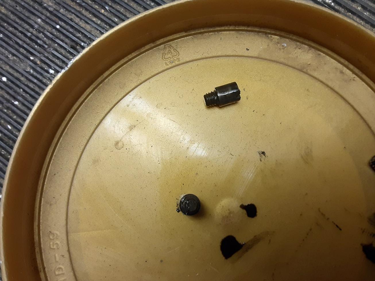
Yup, I think it was some type of thread spool holder and the thread came out the bottom hole.
-
Well, it turns out that a good chunk of the answer to my question was in a later issue of a 29K operation manual that came with the machine. It is so soaked with oil that the pages are all translucent. I actually was looking at it because I was looking for thread size limitations. Back page had a great diagram showing the adjuster on the end of the piston. Armed with that I was able to watch the lever move and can see what the parts need to look like to allow adjustment of the lever travel. I can also see how the adjustment can alter the tightness of the stitch as well as the centering of the lock. I'll post pictures of the part when I get around to making them. The tensioner on the side of the machine for darning was missing. I did find one of the discs installed in the top tensioner as mentioned before. I cannot get a thread gauge into the tapped hole in the machine head to measure the pitch. But comparing it visually with my thread gauges, I came to the conclusion it is either and 8-36 or 10-36 thread. Well, it appears it was an 8-36 and some ham fisted rebuilder or previous owner stripped the thread in the head. I machined a 10-36 thread and it would not fit. The 8-36 fit and then stripped with minor finger pressure twisting the screw. So, I'll probably just tap it for 10-32 and make a new stud for the tensioner that fits. I did some practice sewing to check my stitch quality and pitch. Set at 5 SPI, I get about an 8 to 8.5 SPI. I feel play in the bell crank so I need to replace it or repair it. It's not obvious how the internals come out of the sewing head. I see a couple of screws that probably hold everything in place. But I need to study it a bit before taking it apart and watching it barf the internals all over the floor. Actually, I'm a white towel guy and that will get laid on the table before anything is removed. If anyone know of a tutorial on how the head comes apart, that would be helpful. I'm going to search the web for info. I may just weld up the worn area of the bell crank and reshape it to restore the max thread pitch capability. I did figure out a way to revive the treadle to see if I liked it. I had miles of oxygen tubing left over from my Mom who died of cancer 30 years ago. It's quarter inch clear plastic tubing. It is not too stretchy and figured it would do for a test run. Fit a piece to my machine, which requires 7'-6" of belt due to the tower extension, and used a piece of plastic covered cable (from the dog's run) as a coupler. Works the nuts. Really prefer the treadle over the wimpy electric motor. Speed is perfect for a newbie like me and the control is excellent. So, if anyone needs a new treadle belt for a 29K machine, go to your local hardware store and buy some 1/4 plastic tubing (19 cents/foot locally) and make yourself a new belt. Bet it will last a lifetime.
-
Okay, thanks. It's just under an inch in diameter. Could be a container for a small spool of thread and you pull it out thru the hole in the bottom. That thought just occurred to me as one of my many dormant synapses decided to fire.