Kawakneurder
Members-
Posts
24 -
Joined
-
Last visited
Profile Information
-
Gender
Male
-
Location
Netherlands
Recent Profile Visitors
The recent visitors block is disabled and is not being shown to other users.
Kawakneurder's Achievements

Member (2/4)
-
This stuff should be available in the user manual of the machine. Have you tried sending durköpp adler (or your local official DA distributor) an email? They are generally very helpful with questions and are willing to send the service manual for any machine they still have information on.
-
How to remove handwheel on Durkopp-Adler 69
Kawakneurder replied to paloma's topic in Leather Sewing Machines
On aliexpress the pulleys are widely available. I recently purchased this one in particular and have found it to work quite well, plus they are extremely affordable. So far I have not found anything I can fault it for. Probably these are the exact same pulleys you buy from shops in the west, except now you buy straight from the manufacturer and thus they cost 10x less. 45mm seems to be the smallest size available, and as far as I know the shaft diameter is pretty standard on sewing machine motors, so it should fit yours as well. -
How to remove handwheel on Durkopp-Adler 69
Kawakneurder replied to paloma's topic in Leather Sewing Machines
Let me guess, the screw in the middle of the wheel? I have forgotten that one a few times, wondering why it wouldn't come off after taking out the set screws -
Consew 206RB-5 Index Marks Question
Kawakneurder replied to earla's topic in Leather Sewing Machines
There's two excellent videos here on youtube from a guy called MTRC Crane. I accidentally stumbled upon these videos, but these seem to show all the adjustments that you have to do on this machine. Maybe you can find some information on the marks in htese videos. -
Durköpp Adler 267 Alternating feet adjustment
Kawakneurder replied to Kawakneurder's topic in Leather Sewing Machines
Okay, after doing a bit more reading, and with some help from this excellent video from MTRC Crane on youtube, I have figured out what to do I think (The video is about the Consew 206RB, but all the adjustments are very similar). If anyone with more expertise realizes this is incorrect, please do correct me. This is basically correct afaik This adjustment seems to be just for the lifter on the back (or knee lifter). So you should put the block under the outer presser foot. This also means that the position of h, and the position of the needle do not matter. This is mostly correct it seems, except for step 1. Apparently you are not supposed to put h all the way up on the track, and indeed if I put it about halfway, I already have a lift of about 7mm. If you do this, the machine doesn't bind up, and does walk. If I adjust the machine like this it does run, and when I turn the hand-wheel it does feel like a smooth motion. However, I can't give it a 'spin' with the motor attached, and have it keep running because of inertia. It does immediately stop. Is this normal for walking feet machines? Or should it be spinning freely for 1 or 2 stitches? -
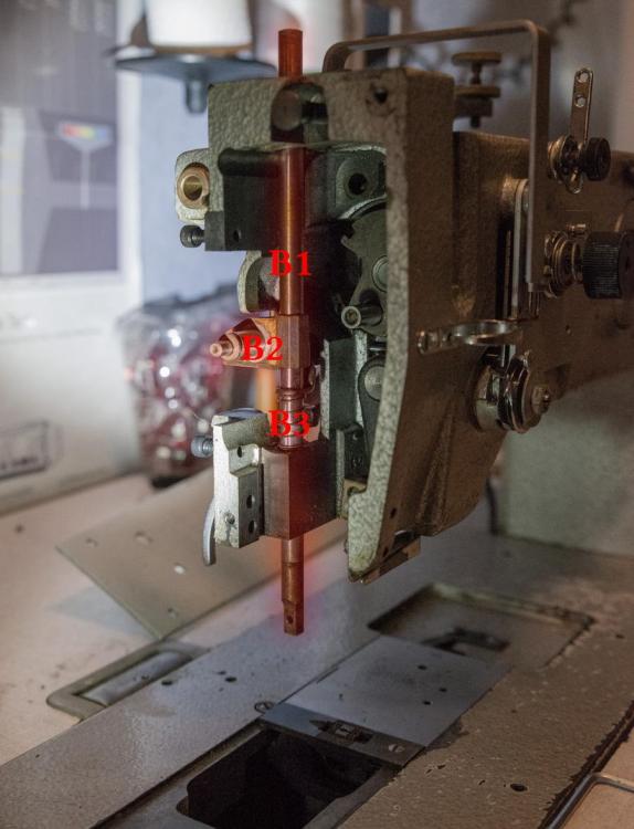
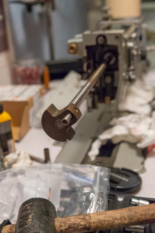
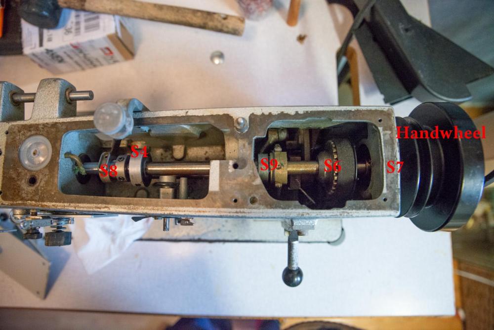
How to remove the upper shaft of a Durköpp Adler 267 (part 3 of 3) Step 7: Removal of the presser bar (for the outer foot) The shaft applying downward pressure on the outside foot is held between two holes, and connected to an assembly used to set the foot height (B2). Firstly, if you haven't already done so, remove the outer presser foot and the screw used to hold it in place. B2 can then be screwed loose, after which the whole shaft B1 can be lifted out of the machine through the top (you might need to unscrew the top bearing). Be sure to catch the assembly B2 and spring B3! They are not held captive. Note also in the pictures, that generally if I remove a bolt I immediately put it back into the machine. This is a little trick from motorcycle maintenance, it makes it much easier to put the right bolts back into the right spots. It also prevents you from putting everything back together and then discovering you have 'left over bolts/screws' (very common with laptops ) Step 8: Removal of the shaft Finally the shaft can be removed from the machine. Before starting it might be a good idea to have some tiewraps handy. Now start to remove the shaft, it might need some 'percussive maintenance' to get moving, so a rubber hammer and (soft, preferably wooden) punch are handy here too. Be sure that none of the couplings onto the shaft are skewed though! If they start sitting skewed on the shaft, and you start hammering the shaft, you can do some serious damage! Take it slow and make sure everything slides smoothly. Now, as soon as the gear with the belt comes loose (S6), make sure it does not fall down. Immediately secure the belt to the gear with a tiewrap. Then, whilst still holding onto S6, try to flip the machine and tie a tiewrap around the belt on the bottom gear too, this ensures that they keep synchronization. If the belt slips off it is not a big deal, but you will need to redo the hook timing. Step 9: Replace your parts Shift out the shaft as far as it will need to go, and do your thing. To put it back together, follow the same steps as shown here, but in reverse. Step 10: Re-synchronize/tune the machine After everything is back together, the timings of the walking foot, needle and hook are most likely off. Go through the procedures in the service manual to get these right. I do not feel confident enough about this to comment on this, as I am still struggling with this myself. Step 11: Crack open your well deserved cold one and enjoy Voila! 10 step plan completed. You have successfully removed the upper shaft, replaced your part and put it all back together! This step should be obvious
-
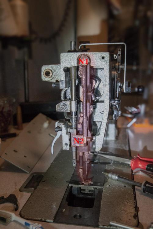
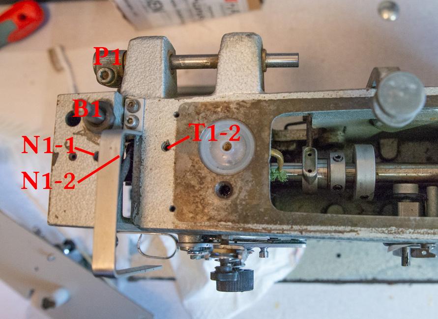
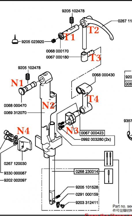
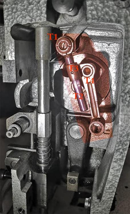
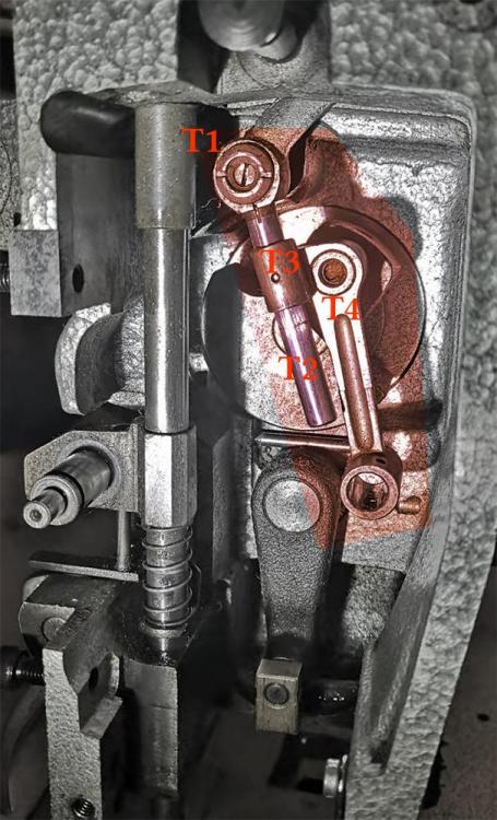
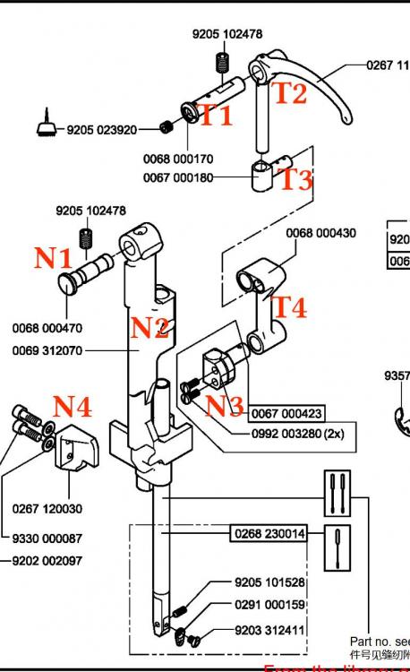
How to remove the upper shaft of a Durköpp Adler 267 (part 2 of 3) Step 5: Removing the needle-bar and inner presser foot assembly If done properly the entire needle-bar and presser foot assembly can be taken out. As shown, you do not need to remove either the foot or the needle for this to work. Firstly remove the setscrew N1-1 at the top of the machine. Now pin N1 can be taken out of the machine. It is helpful to know that it can be pushed from the opposite side of the head (hidden in the picture, location N1-2). If it is particularly persistent, use a hammer and punch (preferably soft punch). After this is removed, the whole assembly N2 should just slide out. Note that there is a little square (copper?) guide block which synchronizes the top foot to the bottom feed dog. This part is not held captive, so make sure this doesn't disappear into some dark corner of your room if it falls off. Step 6: Remove the take-up lever linkage assembly In a previous post I have already highlighted how to do this. First remove set screw T1-2. Now only T1 is holding the linkage in place. If T1 cannot be pulled out, you can remove the little set screw inside T1, and screw in an M4 bolt to get a better perch on the pin. With T1 removed, the whole linkage slides out relatively painlessly.
-
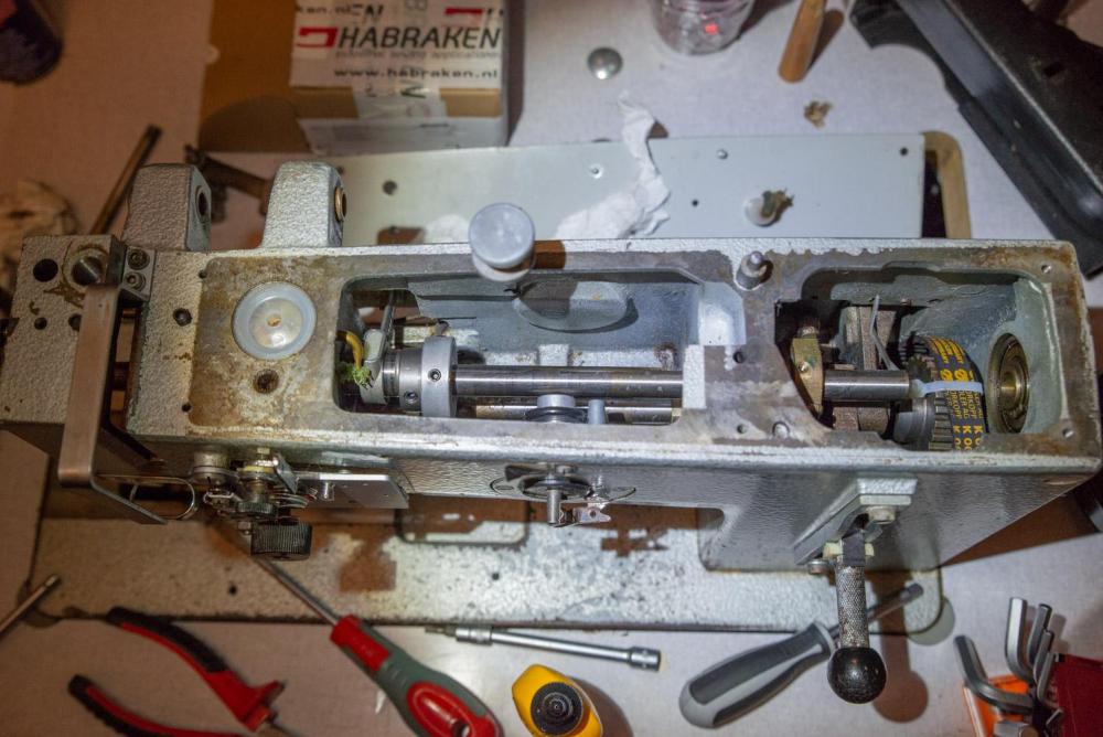
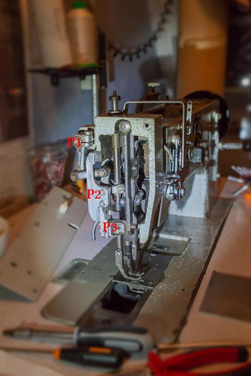
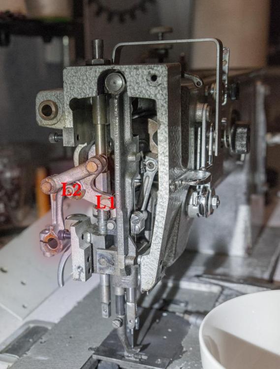
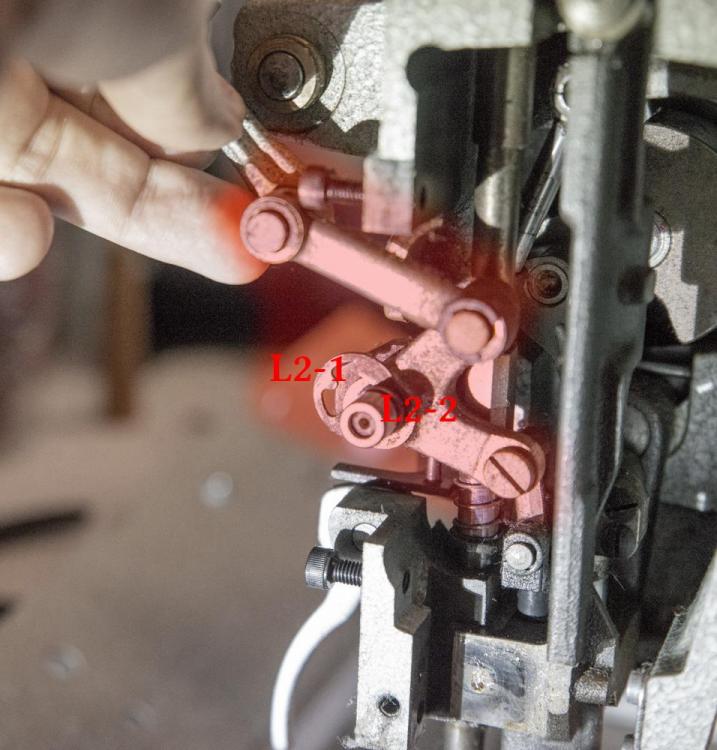
How to remove the upper shaft of a Durköpp Adler 267 (part 1 of 3) Step 1: Remove the following items (not shown in images because trivial): top leaf spring keeping pressure on the feet the top cover the belt cover + belt Front head cover Step 2: Preparing the shaft for removal: Loosen all the set screws that attach to the internals of the shaft (In the image: S4, S6, S7, S8, S9, Handwheel). All of these parts are fixed with two set screws each. \ Step 3: Remove the linkage and structural parts Disconnect P1 from the foot-lift rod (or remove the rod entirely, as you will need to do so anyways). Remove P2, and P3 which provide support for other parts, enabling access to the removal of the foot lift linkage. Note that guide-block P3 is the same as 'N4' in a previous post. Step 4: Remove the foot-lift linkage The foot-lift linkage is now held in place at two points to the needle bar. Firstly at point L1, and secondly at L2. The only thing preventing it from sliding off is a E-clip L2-1 on L2. Before removing the assembly from the sewing machine, be sure to remove the little roller L2-2 as well. It might be more convenient to first unscrew L1, and then slide it off L2. If you do so, the entire linkage can now slide out of the machine in one piece, no need to disassemble the separate linkages.
-
Sailrite Ultrafeed LSZ-1 w/WorkerB motor
Kawakneurder replied to MtlBiker's topic in Leather Sewing Machines
I have always wondered how good the sailrite machines work compared to a 'proper' industrial sewing machine with needle feed, as the sailrites don't have that. Then again, there's multiple youtubers (for example Jason of all Trades that Gymnast mentioned) that swear by them, even-though they have access to industrial machines as well. I suppose that is partially because of the portability? It definitely is a great option if you don't have space for a whole table, as it's either sailrite or nothing. Also, I really enjoy their youtube videos, in which they have tutorials for making almost anything. It's awesome that a company puts out such high quality videos for free. If sailrite had better availability here in Europe I'd definitely buy from them because of this. -
Durköpp Adler 267 Alternating feet adjustment
Kawakneurder posted a topic in Leather Sewing Machines
Hello all, I have recently started to undertake the restoration of a DA 267 machine (some you might have seen this post). During this process I had to take apart pretty much the entire upper half of the machine, so of course after putting everything back together it has to be adjusted again. I went through the whole process in the service manual, and so far it seems that everything is working perfectly except for the synchronization/height of the alternating feet. The service manual is also kind of vague on this procedure, so I thought I might as well check in here, as there's some seriously experienced people on here who probably know the answer. Here's some diagrams from the service manual: So as far as I understand, the following is the procedure I need to follow consists of two main procedures: Setting the presser feet height, and synchronizing the presser feet height. I have gone through the procedure but it doesn't seem to work very consistently for me, and some things are very unclear. Also, the problem I am having right now is that I can get the feet to cycle and feed, but if I set the walking foot height to the upper most position (h all the way up track H in fig 10), the feet give a lot of resistance and feel like they bind or something. This issue I don't have at a lower height, so it kind of points me in the direction that I am doing something wrong in presser foot height adjustment. Anyways, this is how I think the procedures should work and how I do them: Setting presser foot height: What I think is the procedure (what I have done) is the following: Release spring P (fig 9) Loosen clamp w by loosening the two screws Put a 7.5mm height object under the presser foot Press the foot down onto the object, and tighten screws of w again Re-seat spring P (fig 9) Now the presser foot height 'should' be adjusted properly. I have some questions about this though. Firstly, step 3 does not detail under which of the two presser feet you have to put the reference block. Should it be put under the inner, or the outer block? Also, doesn't the position of h (fig 10) and the position of the needle matter for this adjustment? If it does matter, what position of the needle, and what position of h should I use (I assumed for h all the way up, as that is the biggest step height). Synchronizing presser feet height Set h all the way up in track H (i.e. largest step height possible) Observe which of the two feet (inner or outer) makes the taller step Rotate the hand wheel forward until the 'tallest' foot is just above the plate Loosen 'p' in fig 9 Press down the foot, and tighten p again Repeat step 2 to 5 until the feet have the same stepping height I am pretty sure I am doing this one correctly, but I have described it here for completion sake, as it is kind of coupled to the adjustment of the presser foot height. Does anyone know what might cause this binding issue? And can anyone clarify the proper presser feet height adjustment (in particular the conditions such as needle position and position of h for doing this adjustment)? Many thanks in advance -
adler 69 and 67 bobbins
Kawakneurder replied to Cumberland Highpower's topic in Leather Sewing Machines
I believe you are correct with this. AFAIK the 167 has a bigger bobbin than the 67 and probably also has a bigger hook assembly because of it. -
I was correct, the axle is removed via the head. After getting the take-up lever assembly out of the way, the rest is relatively straight forward. Indeed, T1 was the only thing holding in the assembly. To take it out, I took out the little set screw which goes inside the head of T1, and instead screwed in a long M4 bolt. With this bolt I was able to apply some force with a lever, and eventually pop it out. So for anyone running into the same problem, this is a relatively easy and cheap solution. After replacing the part I needed to replace, I put everything back together and took some pictures along the way. If I find some time I will do a short write up for anyone with a Adler or DA 67/167/267 (since I think all of these are very similar). I have already managed to do the hook timing and needle height (thanks for the great video Uwe, much easier to use than reading the service manual, which is quite vague with this), and also at least the walking feet are walking the correct direction. Now I just need to mess with the timing, path and height I suppose. Just following the service manual. Funnily enough, when I got the machine it had the 'wrong' sized needles (135x17). I have replaced them with the recommended DPx35 (134x35) needles, but after checking the timing it didn't seem to need any needle bar height adjustment. The needles are only .8mm shorter (38.1mm vs 38.9mm), so that isn't as big of a difference as I thought it would be, and it does show you can safely exchange the different needles without any adjustment (assuming the machine is properly adjusted in the first place).
-
A short update, I have send an email to DA directly, in the hope of getting some sort of dealer manual (if it exists) or other help with the disassembly procedure. They have referred me to their local dealer, and I have not heard back from them yet. In the meantime, I have come to the conclusion that I might have been wrong, and that the upper shaft must be removed at the head end of the machine, and not at the hand-wheel end. I believe this to be the case because the counterweight seems to be pressed onto the shaft and aligned somehow with the cutouts on the shaft (for for example the belt to the lower axle). Therefore it makes sense that they press this part onto the shaft, before putting it into the rest of the machine, as it doesn't need adjustment. Because I think this might be the case I have begun trying to disassemble the head of the machine. I will try to take some pictures whilst putting it back together so that anyone attempting this in the future will be able to use it as reference. So far I have made good progress, removing the linkage for the walking feet, and the needle/needle-bar assembly. However, I have ran into issues trying to take off the take-up lever assembly. Here is a picture of the assembly (marked as T*) and also the diagram in the service manual: For clarity sake I have also marked the needle assembly parts as N*. Taking off the needle assembly was fairly simple (although not so obvious) by taking out the set screw of N1, and then trying to push it out. For me N1 was stuck, but luckily N1 sticks out on the other side of the head so with a punch and some elbow grease you can still work it loose. It seems that the take up lever assembly is fixed in a similar way, with T1 being held in place with a set screw. This set screw is easy enough to remove, however I was not as lucky as with the needle assembly because T1 seems to go into a blind hole, there is no way to use a punch to persuade T1 to come out. T1 itself has a screw inside (visible in the picture) but this is merely an access hole to put in some oil. T1 itself also seems to have a cutout for a flat-head, but I have not managed to turn T1 itself. I have tried pulling on T2 with quite some force, but it doesn't seem to budge. Does anyone have any tips on removing the take up lever assembly? Or am I doing it wrong? Cheers
-
This is indeed what I thought (and hoped for), but sadly it is not the case. When I run my finger nail along the surface you can feel the pitting, and trying to clean it up with a variety of chemicals (including IPA, WD40, general purpose cleaner and MEK) didn't yield any results. Just to be sure I will try tonight to clean it again. The machine had not been used a long time I suspect, and oiling the reservoir that feeds this bearing is not so obvious. Also, the reservoir feeds through a wick onto a pad onto the bearing. I think this whole lubrication mechanism might have dried up, and if you just add oil into the reservoir without giving it time to soak into the wick and pad, the bearing itself would still be dry. And once such a bearing runs dry and starts friction welding, the damage is already done and beyond repair...
-
Old singers are extremely common, and unless they are a very rare model, or in extremely good condition, they don't warrant a very high price. They don't even mention the name, so calling it 'highly collectible' is not something you should do. Jason Of All Trades recently posted a video about this, also discussing the extremely high (often unwarranted) prices of some 'vintage' machines. Regardless, for 1234$ you can get an extremely good walking foot industrial machine. Unless you have a huge collection and this is like the last machine you are missing and want it in top nick condition, honestly that's way too high of an asking price. Even 675 is on the way expensive end. Even nick condition singer 201's go for way less than that.

.jpg.d60258221c476480a6e073a8805645bb.jpg)
