


friquant
-
Posts
514 -
Joined
-
Last visited
Content Type
Profiles
Forums
Events
Blogs
Gallery
Store
Everything posted by friquant
-
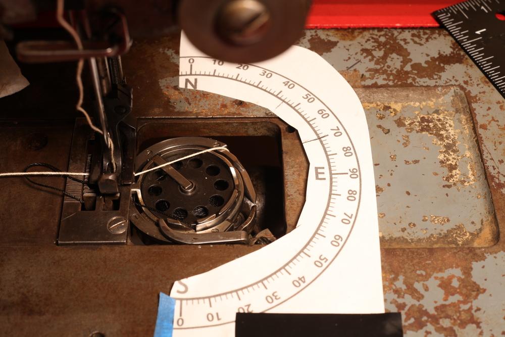
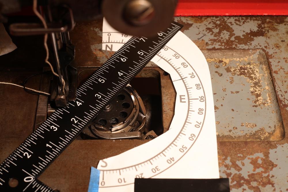
Hook timing...what a drag! You remove some parts, insert a brand new needle, then get out the calipers and measure a tiny rise of the needle bar past bottom dead center. Afterwards, if the machine does not sew well, you repeat the process and hope for better results. That's why I'm going to start measuring hook timing another way---at least on my vertical hook-shaft machines. I'm going to start measuring degrees of hook rotation. Protractor I'll set up my axes like this: 0 degrees: when the hook shoulder is farthest from the user 90 degrees: when the hook shoulder reaches the apex of the hook's journey around the bobbin I'll print this protractor and tape it to the machine bed. Note the origin/center of the protractor is at the center of the hook/bobbin. Note in the photo above, the white top thread is stretched between the throat plate hole and what I've been calling the hook "shoulder". I'll rotate the hand wheel to where the take-up lever is at is lowest point. Then I'll take a measurement of the hook angle from the center of the hook to the hook shoulder. (I chose the hook shoulder because it is the part that actually drags the thread around the bobbin, and it is easy to see from the top.) If you click into this image you can see that the edge of the ruler/square crosses the center of the hook and crosses the hook shoulder where the bit of white thread is peeking out. Note this photo shows a 39 degree measurement. What This Measurement Style Provides: Easy to measure hook timing without removing anything but the bobbin cover plate Easy to visualize where the hook is in its cycle in relation to where the thread take-up lever is in its cycle Easy to make generalizations (I hope) about certain hook timing angles producing certain behavior/symptoms across lots of different machines The timing angle is the same regardless of what stitch length is selected The larger the timing angle, the more advanced the hook timing. (Note with the old/conventional measurement system, larger numbers mean the hook timing is less advanced.) The timing angle is the same regardless of how much the hook point is worn Background / Theory: The hook's job is to grab the top thread and drag it around the bobbin. As the hook shoulder rounds the apex of its path (goes around the right-most edge of the bobbin), that is the farthest that the thread gets dragged through the needle before the thread take-up lever pulls the thread back the other way. The hook shoulder going around the right-most edge of the bobbin must coincide roughly with the thread take-up lever being at its lowest point, otherwise the thread will be tight and the hand wheel hard to turn as the hook drags the thread round the bobbin. Some Data Points and Corresponding Behavior I was working on dialing in the timing on an old Singer, and to learn the machine better (and develop my skills) I was purposefully doing it without referring to a manual. Here are the timing angles on the left, and a description of the corresponding behavior on the right. 2° Top thread tight and grabby as it rounds bobbin 13° Top thread tight and grabby as it rounds bobbin 20° Top thread tight and grabby as it rounds bobbin 44° Most of rounding bobbin is easy...but snags just a bit on the hump by the bobbin tension spring 46° Easy to round bobbin. Good clearance between nearly-formed loop and hook 51° Easy to round bobbin. Minimal clearance between nearly-formed loop and hook 70° Very easy to round bobbin. Negative clearance between nearly-formed loop and hook. (The hook stabs into the nearly-formed loop and jams the machine.) In this round of measurements, the 46 degree setting was my favorite. (I did not get more measurements between 30 degrees and 44 degrees because I was having trouble getting the worm gear slid into position.) Making Generalizations By trying out various timing angles, I was able to observe certain behaviors and put them on my mental map of what causes those behaviors. (And can hopefully fix some of the tendencies from the "70°" row that I've been having on a different machine!) Hope this is useful to someone wanting to understand not just how to set hook timing by the book, but how to react to certain (mis)behaviours, and possibly how to design a sewing machine 😀
-
I spent a day with a binder on my pfaff-545 and could not get the bottom and top sides to be even. I conjectured that to get them even the entrance runway (the zig zag of wire) would need to be horizontal, whereas mine was canted upwards to clear the flatbed. My best plan at the time was to stitch from the wrong side of the fabric, since the bottom of the binder always had less coverage than the top. That way the stitches on the right side of the fabric could be close and tidy to the edge of the binding. I bought two binding attachments with my JL 341, but have not used them. When I ordered them they were specific about asking what kind of tape I wanted to use---both its width and its thickness.
-

How to Subscribe to Everything in a Single Forum
friquant replied to friquant's topic in Computer Help
That does seem to be the pattern for the other missing notifications as well. I'll figure out a game plan for those 🍹 -
Is following a subforum expected to be reliable? A month or so ago I set myself as following the Leather Sewing Machines subforum. Since then I've only been reading things I see notifications for, which I assumed would be all the new posts in that subforum, plus replies to things I've replied to. Today I stumbled upon some new posts in the same subforum that I had not seen and that did not show up in my notifications. Example post that I did not receive a notification for: https://leatherworker.net/forum/topic/131587-binding-attachment-from-china/ That was posted on Thursday. Here is a screenshot of my notifications for thursday @Johanna for visibility

-
I don't have any experiece with a Pearson #6, but if you can post some videos of what you're seeing maybe someone here can make sense of it. In general if it picks up the thread when there is no material under the foot, but doesn't pick up the thread when there IS material under the foot, I would think it's a timing issue. Just speculating. On my vertical-shaft machine I can take the cover off the bobbin and watch the hook go around and see it drag the thread around the bobbin. You may be able to do something similar with your setup to figure out what/when it's missing.
-
P03 is probably needle-down position (mean how far the handwheel turns from needle-up position to needle-down position) P10 is supposedly for breaking in the machine. I forget where I read that. This Stitchman Servo: The missing manual may give you ideas about some of the others.
-
The motor howls---I suspect it's a bearing inside the gearbox that has a pitted race. I have not been able to get the front cover off the gearbox. Next time I'll tap it with a sledgehammer to knock it loose. The VFD has a noisy fan too, but the motor howl is the bigger problem.
-
Thanks! I've been enjoying it 🤠 None so far. My duty cycle is quite low in general as I'm typically spending much more time thinking about sewing and planning the design than I am actually stitching. The only instances where I can see a good use for going ultra slow is at the start of a seam (when I'm scrambling to make sure I've got the thread held down while also driving one-handed), and at a corner or end of a seam when I might slow down to make sure I bury the needle when I let off the gas. The middle sections, especially of straight seams, warrant higher speed else one gets bored. I conjecture that a few seconds of ultra-low speed at the beginning and end of each seam, even if they do cause extra heat (I'm unclear on this point) won't cause enough extra heat in those few seconds to cause any trouble---the heat will be absorbed by the mass. As far as what could potentially overheat, and how to measure & test that, I'm open to suggestions. VFD This VFD has a temperature sensor for itself, and you can specify what temperature is too hot and it will disable at that temperature. Motor This motor does not have a temperature sensor that I know of. I could imagine nesting a thermistor between the coils of the stator and running the thermistor wires out through the electrical box along with the power wires. I have not adjusted the volts-per-hertz settings at all yet, but that's worthy of testing out. I wish this VFD had a setting for overall reducing the amount of current (torque) going to the motor, but I haven't found a setting for that yet.
-
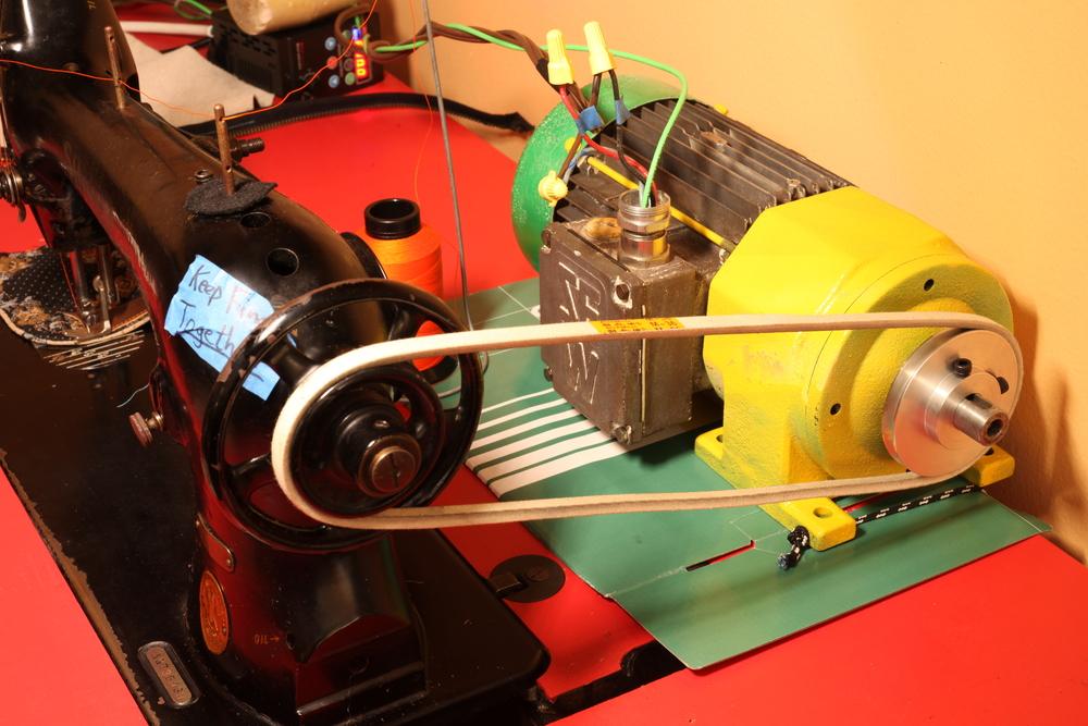
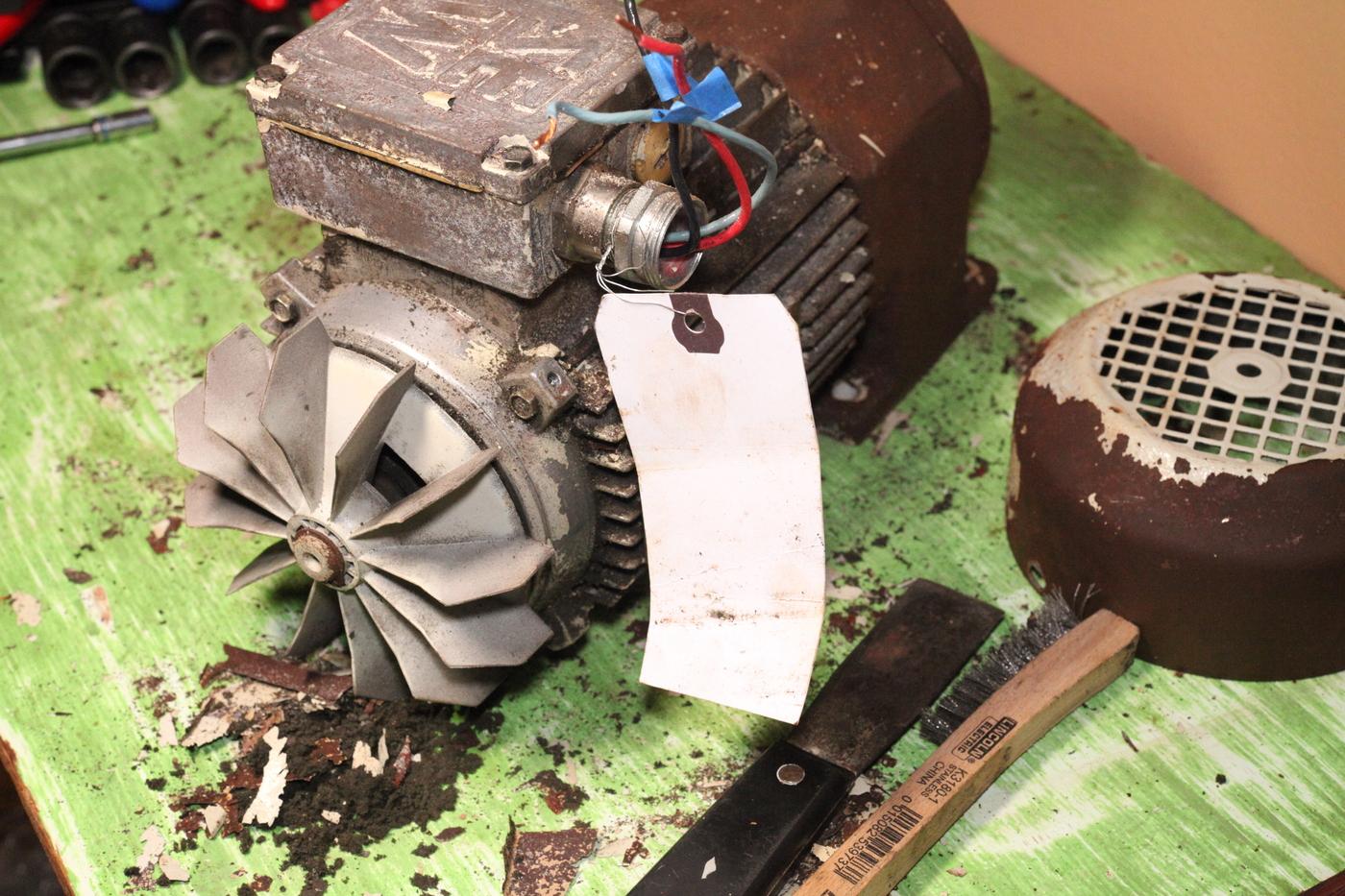
Got it cleaned and painted Here it is set up temporarily with the Singer 31-15 And a video of how it operates using the TIG pedal's contact switch and potentiometer to activate the VFD when you step on it. vfd-intro.mp4 Would like to find a reliable, inexpensive source for these gearmotors so we can set up a recipe or parts list for anyone who wants to go this route.
-
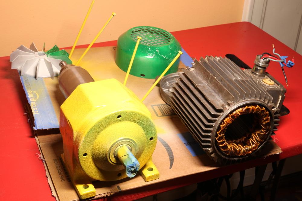
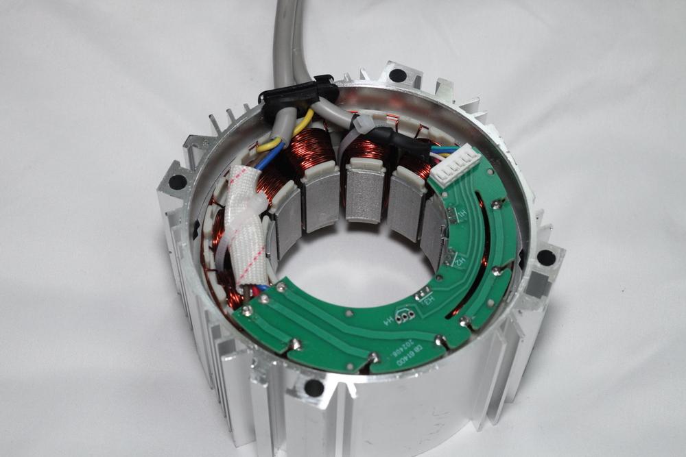
I recently found this same cooling design on an industrial motor. In this photo, the cover (far right) has been removed. So I asked my favorite AI about it, and I found this page: https://en.wikipedia.org/wiki/TEFC_motor
-
Singer 132k6 capabilitues and upgrades
friquant replied to Ed Neil's topic in Leather Sewing Machines
Re: Clutch motor It's a 110V motor. It's normal/fine for switches and capacitors to be rated for higher voltage that the actual use case. But even if you did want to use a clutch motor, this is not the one to use because it's a 2-pole motor (3500rpm) instead of the 4-pole variety which are only 1750rpm. Good move on the digital servo. Is it a cylindrical shaft 15mm diameter? If so, you can get a 45mm pulley for that here: https://www.ebay.com/itm/376135081840 which will slow it down considerably. Re: Belt slipping I would buy a new belt. The belt looks all dried out (less grip) and looks to be too narrow for that pulley. V-belts need to be pressing against the walls of the pulley to get the best grip. I've been buying belts like this one: https://www.amazon.com/dp/B0BK1FQHRR but I suspect that a 3/8" automotive (rubber on the outside) belt would be the grippiest. -
Nice photos!! You can check whether bobbin is loaded properly before making any stitches. Install the bobbin and bobbin case cap. Put the latch down (and make sure no thread under the latch!) Bring up the bobbin thread Pull the bobbin thread for a few inches. You should feel a gentle resistance the whole time you are pulling. If it snags, something is not right.
-
Singer 132k6 capabilitues and upgrades
friquant replied to Ed Neil's topic in Leather Sewing Machines
@Wizcrafts blogged about the 132k6 in his My history with leather sewing machines blog -
Singer 132k6 capabilitues and upgrades
friquant replied to Ed Neil's topic in Leather Sewing Machines
Can you send us pictures of your current setup? (Motor, pulley, belt, machine) Also photos of your old motor, control box, and nameplate if it has one? (If you want help diagnosing the old motor, that is) New leather belt? Old leather belt? I like having my belt tension set just high enough to go through my thickest material, that way I'm less likely to break things. My belt is not very grippy, but I'm considering getting a regular rubber automotive belt instead of these cloth-covered belts I've been using. Not sure what other folks are using for belts. -
The boon of synthetic motor oil is that it SMELLS GOOD. Or doesn't smell bad, I should say. I can't say the same for regular motor oil.
-
To find out what is binding up, you can turn the handwheel very slowly and pay attention to which part of the circle it binds at. Binding typically means something is trying to move farther than there is space to move. You can start taking inspection covers off to see the linkages that are at work. I've had a machine bind when it tried to lift the needle bar too high, and the needle bar ran into the head unit. Or when the latch opener tried to open wider than there was room for. Not sure what you'll find on this machine, but if you start exploring hopefully you can find some clues. While you're at it, you can oil the linkages 😀
-
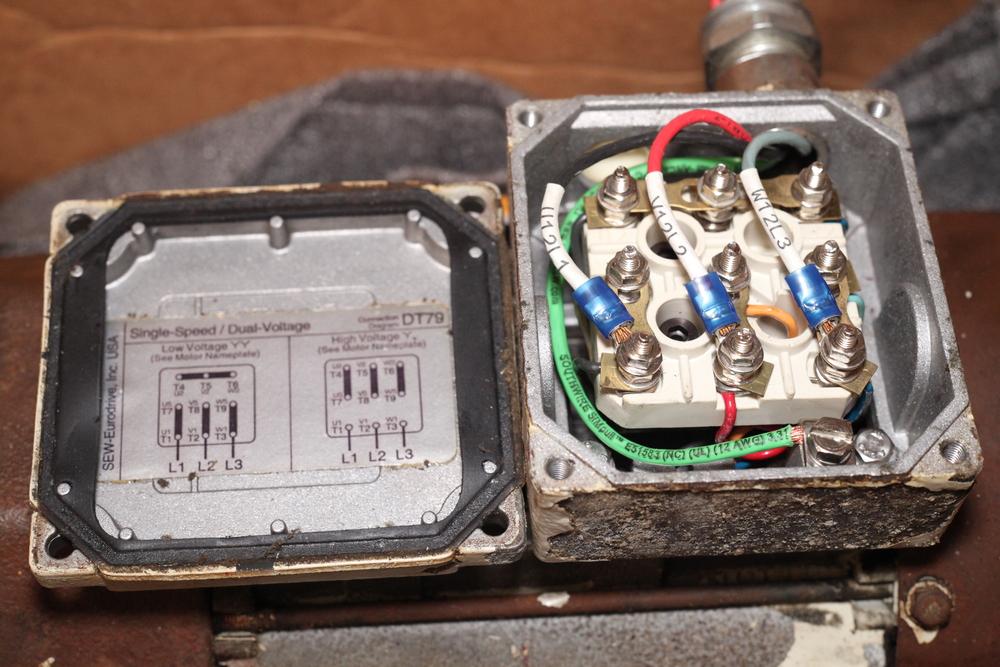
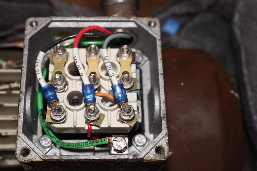
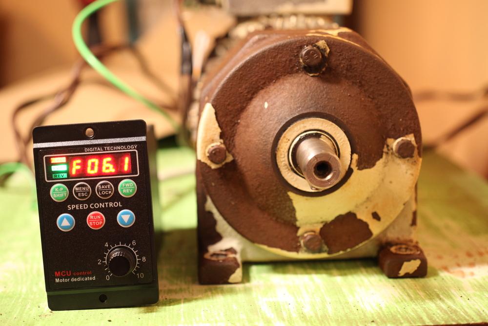
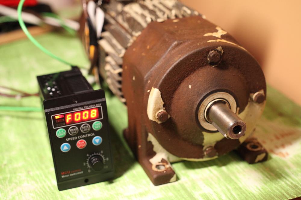
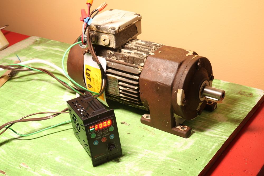
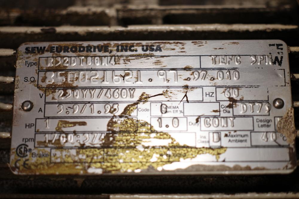
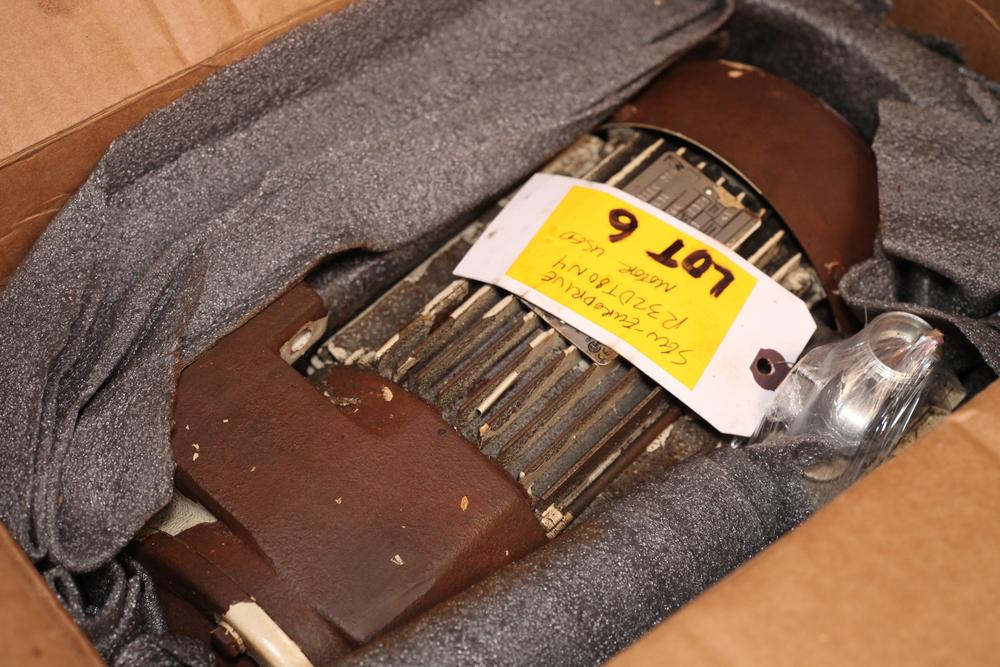
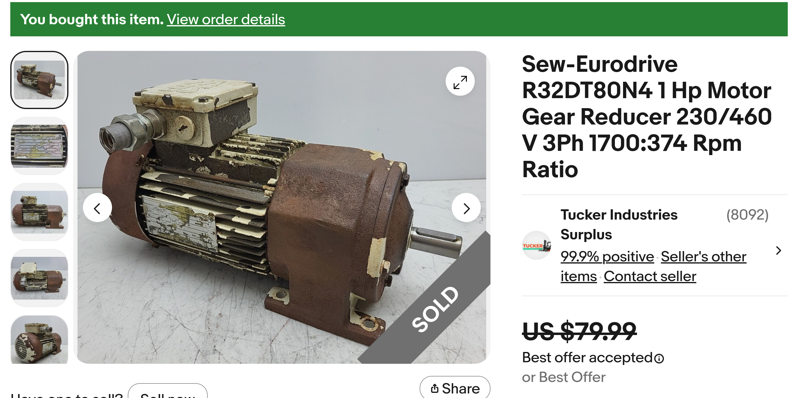
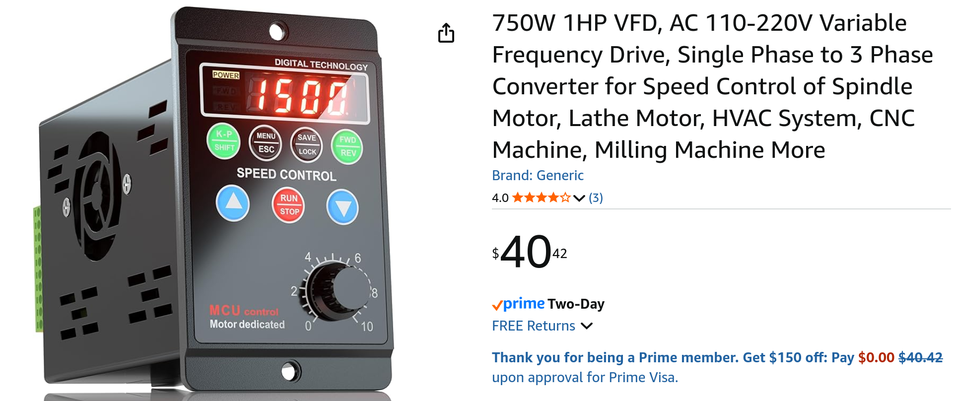
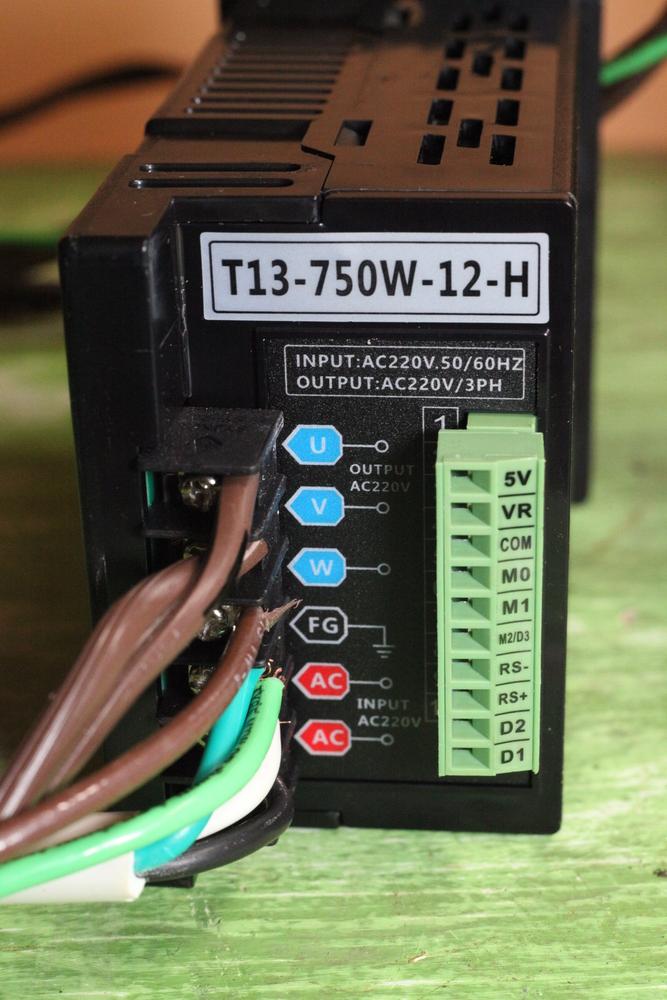
Today I was able to bench test my first 3-phase AC gearmotor running on VFD. It's a foot-mounted Sew-Eurodrive 1-horsepower with 4.5:1 gear ratio. Gearmotor A four-pole AC motor typically has a speed around 1500 rpm when fed 60Hz power from the wall. With the 4.5:1 gear reduction, that puts us around 330rpm with wall power (60Hz). So long as the AC motor is 3-phase, we can add a VFD in the mix to control the frequency of the power going to the motor. And voilà, we have a motor that can go anywhere from 0rpm up to 330rpm. At least that's the theory I've been reading for the past few weeks...I hadn't seen any of this in action until today. This ragamuffin came to me by way of ebay. Here is the original listing. I'll include a screenshot of the listing because these listings go away eventually. This motor is bigger than I needed. 400 watts (1/2 horsepower) or maybe even 100 Watts (1/8 horsepower) would suffice. But this one I found for a song, only $65 after shipping. I did verify that it was actually 3-Phase before buying. (See the "3PH" in the upper right corner of the motor nameplate) The box arrived a few days later. It was packed cozily in cardboard and foam. The outside of the motor is gritty. Perhaps it's been running in a moist environment. The ad says it was taken from a running system. I'd like to clean it up and paint it, but I want to see it run first.. The wiring was set up for 380V, so I reconfigured according to the diagram for the 220V that my VFD will output. (My VFD takes 110V single phase as input, and outputs 3-phase in the range of 220V.) Here is before and after, note the copper strips have been repositioned under the nuts to effect the wiring change. VFD The VFD (variable frequency drive) I've actually had for a couple weeks while I've been looking for motors. But I've never owned any 3-phase equipment so had no way to really test the VFD, hence the excitement when the gritty box finally arrived. 🤪 Here is a link to the VFD I'm using: https://www.amazon.com/dp/B0D53Z7RZ5 And a screenshot: Here's what the back of the VFD looks like. The two red "AC" labels are for neutral and 110V single phase input. FG is ground, connecting both to ground in the wall outlet and to the ground on the motor. The blue U, V, W are the 3-phase outputs which the VFD can control to be any frequency from 0Hz up to I think 100Hz, which is how the VFD accomplishes speed control on an AC motor which would otherwise be fixed speed. The green strip on the right is for low voltage input/output. One of them can be used with an external potentiometer to set the frequency. I've ordered a TIG pedal for this but it has not arrived yet---So today we'll use the built-in potentiometer/knob on the front of the VFD to control our speed. Bench Test Here we are on the bench: And a video gearmotor-voice-01.mp4 Many thanks to @GerryR who has fielded a LOT of questions from me as I've been pursuing this journey.
-
Anyone taken a cheap servo motor apart?
friquant replied to AlZilla's topic in Leather Sewing Machines
When I was in there, I found three hall sensors in position to read the permanent magnets of the rotor as they go by. I should have worn gloves when I put it back together...those magnets are vicious, and I got pinched. -
Mine has that too--- paddles running next to the aluminum case, shrouded under some plastic. I think simply removing the plastic cover would be a boon...
-
Option C : Clutch Motor See the parent article: Choosing a Motor Online mostly you will see clutch motors disparaged as a thing of the past, going too fast, with little control. Yet there are ways to tame them by slowing them down (gear reduction and/or VFD) and getting better at feathering the clutch. 1. What is a clutch Just like in an old school automobile with a manual transmission and a clutch, a clutch in a sewing machine motor allows the motor and the sewing machine to move at different speeds. The pedal motion is opposite that of an automobile though— on a sewing machine you press harder to achieve full engagement, and let off to stop. 1a. What is the clutch made of The clutch typically has a cork surface pressing against a steel pressure plate. 1b. Why do they go so fast Not all clutch motors go the same speed. A clutch motor is typically run by an AC induction motor. The no-load speed of the motor is determined by the input frequency (typically 50Hz or 60Hz) and the number of electromagnetic poles (how the motor is wound). The clutch motors I’ve seen are either 2-pole (about 2800rpm @ 60Hz) or 4-pole (about 1400rpm @ 60Hz). Notice one is twice as fast as the other. You want the slower one. 1c. How to reduce the maximum speed Here are some ways you can reduce the maximum speed of the machine when using a clutch motor: Get a 4-pole motor instead of a 2-pole motor. Buy a 45mm motor pulley (the pulley that goes on the end of the motor) for about ten dollars. Add a gear reducer (about $110 for 3:1 belt gear reducer). Get a 3-phase clutch motor, then reduce the motor’s input frequency using a VFD, which will reduce the motor speed proportionally. 1d. How to Make it Easier to Drive First slow it down so that its maximum speed is actually of use to you. That is, so that on your long straightaway runs you can comfortably be full on the gas. See previous section. Reduce the amount of belt tension at the clutch motor pulley to be just enough to go through your thickest material—this helps prevent machine breakage if anything like your hook gets bound up. It also means there will be less force (and therefore less friction) on the main sliding part of the clutch actuator. You want as little friction as possible on the main slider, because friction here means the clutch won’t back off when you back off, and it will be harder to control. Take the clutch off the end of the motor. Clean all the pivot points and the main slide sleeve. Clean them up with sandpaper and/or a file if they have rough spots. Grease all the pivot points (and especially the main slide sleeve), and put it back together. (Oil is not as good as grease when it comes to low friction at very low sliding speeds) Once your clutch is back on the motor, pull down on the actuating arm. Then release some pressure on the actuating arm. It should back off a little every time you back off a little. If not, see previous steps. Set the machine for a short stitch length, and make some practice runs (with or without thread). Experiment with how much leverage the treadle has against the actuating lever, and find what works best for you. Experiment with varying levels of spring tension on the actuating lever. (Optional) Add a heavier flywheel to the motor pulley. (My Singer clutch motor has two flywheels: A seven pound flywheel connected to the motor that is spinning constantly, and a half pound flywheel right next to the motor pulley. It’s the one next to the motor pulley that you want to increase—like adding a low pass filter to the system.) (Optional) Wiz recommends greasing the clutch surface, but I have not tried that yet so I don’t have any data. 2. Is a Clutch Motor the Right Motor for Me? Choose a clutch motor if: You already have a 4-pole (1400rpm) clutch motor and are willing to gear it down to an appropriate maximum speed You can acquire a 3-phase, 4-pole clutch motor (allows using VFD to slow it down) You like driving a manual automobile transmission You appreciate the extra challenge You do most of your sewing at a single speed. That is, with few fluctuations in speed. If you are willing to use the hand wheel to provide the precision that you need at the end of each seam. (A well-adjusted clutch motor can get you close…but you’re on your own with the hand wheel to square it up at the end) You are good at adjusting things You are willing to disassemble and grease the main slider You don’t want or need a needle position sensor You like the droning sound it makes (just like an old school table saw or belt sander)
-
Here's a manual: https://www.manualslib.com/manual/505004/Pfaff-145.html#manual Here's a guide to the numbers and letters: https://leatherworker.net/forum/topic/89283-an-introduction-to-the-pfaff-numbering-system/ Here is a good video by Uwe on timing in general: https://leatherworker.net/forum/topic/36127-pfaff-545-safety-clutch-and-timing/page/2/#findComment-442262
-
The visual of the dual belts running up the right side is picturesque! Congrats on getting it up and running 🌻
-
Anyone taken a cheap servo motor apart?
friquant replied to AlZilla's topic in Leather Sewing Machines
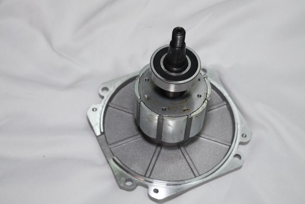
This is the stator and rotor from my "stitchman" digital servo. Only took about fifteen minutes to get it apart with a #2 philips on the screw gun, then a screwdriver and wrench to pry the plates off. Those permanent magnets are no joke!
-
Universal motors are all brushed. My universal motor came with extra brushes even. About half the digital servo motors I see advertise as being brushless---the others don't say. I took the motor apart today on my "stitchman" digital servo and verified that it has no brushes. If anybody has a digital servo with actual brushes inside, I'd be interested to hear.

-
I've started to distinguish between digital servo motors and universal motors with triac speed controllers. Unfortunately, both are marketed as "servo motors".