


Ole South
-
Posts
237 -
Joined
-
Last visited
Content Type
Profiles
Forums
Events
Blogs
Gallery
Store
Everything posted by Ole South
-
My McKay 77 seems to like a combination of 30w Synthetic motor oil and sewing machine or mineral oil. I also use it on a seldom used Landis K12 as well. They both set for periods between high usage. The synth oil doesn't seem to get slung(sp? slinged?) around as much. And yes, grease... fill the cups and thinly on the bearing and ride surfaces. I have a lot of HS red synthetic we used in motor generators that doesn't cake up like the old stuff does. It's probably way over-kill but it works and has lasted well for the last 10-20 years. I'm in the SE U.S..... when humidity+dust=rust... grease is a must (and yes I know there are products made for rust prevention but this is a lube question)
-
Have you checked the basket/hook retaining set screw?
-
6 3/8" x 9" (in plastic w/fused seams) 161mm x 225mm Front keeper 6 3/8" x 4" Back keeper 6 3/8" x 3 3/4" You will (of course) have to adjust these dimensions by your stitch allowance and leather thickness.
-
Singer 29-4 and Adler 30-1 & Kunpeng Feed Motion Rebuild
Ole South replied to Ole South's topic in Leather Sewing Machines
Hmmm... only allowed ONE upload? That pix is only 27.5kb??!!?? -
Singer 29-4 and Adler 30-1 & Kunpeng Feed Motion Rebuild
Ole South replied to Ole South's topic in Leather Sewing Machines
Feed motion ring: Left to right … 29K-60 original, Kungpeng FMR assembled, Roller assembly kit(?), Bare FMR as shipped. Note the difference in length of the two Kungpeng castings. More to come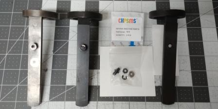
-
Yep, appears to be 3/32" round pin with the sides filed flat to accept the spring slot. Use a piece of brass rod as a replacement slightly longer than needed, strike the replacement pin sharply to blind rivet set it and dress with a file. The pin sits about 1/8" proud.
-
(@Constabulary) Harris finally retired, Pilgrim is no more... I think Wes(?) at Shoe Systems Plus picked up a lot of Pilgrim inventory, unfortunately he told me most of the patcher inventory went to metal recycler. What a loss.
-
Actually, an established cobbler should(might) have a Landis or McKay insole stitcher BUT.... In most cases it will probably be a chainstitch rather than a lockstitch (insoles need "stretch" a bit, chainstitch allows this, lockstitch inhibits. There is, I believe, a Landis insole stitcher that is lockstitch but not as common as McKay style. Chainstitcher probably wouldn't work in your project as the "loops" are your top stitch, inline stitches will be inside your case. Its a single needle(awl), single thread machine. The horn on my McKay is approximately 1/2-5/8" wide. Thread is usually linen (black or white) but 403wt poly might work for short runs.
-
Without pictures it is hard to help but... 1.Compare broken lever profile and thickness with your replacement part, often some grinding/filing/polishing is necessary. 2. Clean receiver area in needle bar driving lever. Remove gunk and foreign objects trapped in there. 3. Broken pin: file broken pin top flat (even if you have to remove a little of the casting) center punch the middle of the old pin and carefully drill out broken piece. You should feel when the drill bit bottoms. Replace pin with brass rod (available at most hobbyshops) I'll check drill bit and rod diameter on my 29-4 (cir1915) later today. I'm thinking 1/16-3/32.
-
Singer 111W155 skipping stitches Help!
Ole South replied to paqman's topic in Leather Sewing Machines
HONEYSEW HOOK+BOBBIN CASE - THICK SHAFT 240558 10655 For SINGER 111W155 CONSEW 224 225 226 https://www.amazon.com/dp/B01LCWD4QG/ref=cm_sw_r_sms_apa_i_SkqAEb19FVC86 This is proper Hirose hook for 111w155, I just replaced one earlier this month... First set screw (turning hook cw, handwheel toward you) goes into notch. Mine had a rounded set screw and a ball bearing instead of a pointed set screw. -
(Full disclosure: I know parts for both models' are pretty much discontinued for the most part but this was a foray into what may or may not work ) I just completed partial rebuild of each model, 29-4 circa 1915 and Adler 30-1 circa "who knows"(black paint/cast iron stand, no decals) feed motion area and thought I'd pass on what I found. Stitch length was far from optimal but little or no play in either of the machines' Driving Lever(s) so I felt driver cam was within functional specs. I noticed Kunpeng Sewing(CKPSMS) sells both a Feed Motion Ring (simanco 82053) and Bell Crank Lever (82167) on E-bay. Prices were reasonable so I bought 2 Feed Motion Rings and Bell Crank Levers to see if they would work. Feed Motion Ring The Feed Motion Rings came without cam follower rollers (they now sell them as a set) so I contacted CKPSMS outlining the issue but got no response. A couple of months later I see the roller and stud assembly (ckpsms #1816) listed at a disposable price so I purchased two. These rollers are clearly marked as being 10mm dia O.D., the description and pictures of the assembly are completely accurate. Being lazy, (I prefer to think of this as "Time Efficiency" but....) I mic'd the roller (rather than the Feed Motion Cam Wheel race the roller rides in) from a well-worn 29K-60 sixty-something year old original Feed Motion Ring I'd previously replaced at 9.79mm O.D. thinking 2.0+mm wear was expectable. It's not... at least not for the 29-4 or 30-1. Both races mic out at 9.79-9.80mm. If anyone has a 29K Feed Motion Cam Wheel (p/n 82149) in good shape I'd appreciate the actual race width measurement at the narrowest part for comparison. I'm guessing the original Simanco roller was probably 25/64" O.D. (ish… mebbe??). The problem doesn't end there; the replacement roller stud has a cir-clip retaining ring and receiver machined into it extending the roller shaft by about 1.5mm. This doesn't allow the assembled FMR to seat into head casting. The Simanco FMR's I've seen have either a free floating roller or the stud is peened almost flush to capture the roller. Easy enough to remedy with a grinder once a properly sized roller is procured but the mounting nut on the other side may also have to be ground flush. I had a FMR from another vendor (Pilgrim or Shoe System Plus probably) that I ended up using in the 29-4. The Adler retained its original FMR. (a new Bell Crank Lever removed all apparent slop) Bell Crank Lever The BCL worked in the 29-4 but bound the needle bar in the Adler as it returned. A lot of creative grinding/polishing later and a couple screw fabrications* and the Adler too had longer stitch lengths. Basic mod was to remove the gore (sloping metal casting) transitioning from the lever bar to the ring making it a clean right (90 deg) angle and thinning the outer wall of the lever's needle bar guide ring to allow full angular motion. Net-net... I now have 2 new Feed Motion Ring and roller assy's (un-usable) languishing in my spare parts bin and a spare Bell Crank Lever should I ever need them *in my case the pivot screws from the worn Adler BCL were a different thread than the Kunpeng which appear to be 6-40 ncf.
-
Thread stuck to bobbin when pull out the work
Ole South replied to Orrrmygod's topic in Leather Sewing Machines
I stand corrected. -
Thread stuck to bobbin when pull out the work
Ole South replied to Orrrmygod's topic in Leather Sewing Machines
Raising the presser foot should release the upper tension disks... rotating the hand wheel should allow the upper thread to clear the bobbin mechanism (try rocking the hand wheel backwards and forwards as you pull the material free). If that doesn't free both threads then double check the adjustments mentioned. Multiple threads(cut) coming out of the feed dog in your picture, indicates upper thread is still captured by bobbin assembly i.e. shouldn't be more than one thread there (bobbin thread). I will hook the upper thread with an index finger where the thread rises above the tension disks and lash spring and pull some slack after lifting presser foot if top tension is tight so not to stress the workpiece. That's the correct threading shown tho most don't use it. And yes... it will increase upper tension by design. The Singer 111 has that pin on the opposite side of the mechanism and is supposed to be threaded accordingly. The machines will still work if you don't. But it does appear you may have missed a guide out of frame prior to the tension assembly. There is vertical wear indications on the first chrome guide feeding the tension disks and the thread is coming in at a different angle... your thread appears to be riding the casting even tho there is no scuffing of the paint. This doesn't affect or cause your problem but... -
Machine For Sewing Sneaker Midsole?
Ole South replied to Daniel G's topic in Leather Sewing Machines
(A very late response, sorry) I've never thought about trying to use a McKay for side wall stitching but I'll check mine. The biggest problem will be the material advance mechanism... a single pawl that digs into the material and pushes it forward (toward the awl) that likes a pre-cut channel. It is a chain Stitcher but that's not a bad thing in this case. Chain stitch has way more stretch than a lockstitch does and would allow the sidewalls to flex better but will unravel if not tied off or glued correctly and the wrong loose thread is pulled. If you notice, this machine in the video, does NOT pull the lockstitch very tight... you can reduce the size of the shoe by 1/4-1/2 an American Size that way(yeah, I've done that hand-stitching using a saddle stitch :/ ) And yes, a Jerk Awl IS what I usually use to sidewall stitch the toe box if needed. You can go pretty quickly once you get the hang of it. A Speedy Stitcher isn't very useful in the dark confines of a shoe upper. Btw... a McKay (or Champion) model 77(Insole stitcher) and it's ilk will not work inside a boot due to its horn limitations... thus the need for an Outsole (welt stitcher) like the Landis K machines. The McKay is far simpler a machine. -
Make a prototype without wet forming and test. If it's too stiff, skive where you want it to bend a bit thinner the width of the flap.
-
Junker & Ruh S.D. 28 Sole Stitcher
Ole South replied to Bootknife's topic in Leather Sewing Machines
I'm wondering if a Landis K stitcher could be modified to do this now the Protos is no longer made? The standard welt guide on the K-12 is interchangeable but I've never seen a box stitching attachment. Has anyone played around with one of them? -
If you wet formed the flap and it has any thickness (greater than 3-4oz or so) or even worse a lined flap... then you create an internal vs external diameter differential*. Meaning the inside length is shorter than the outside length and when you straighten the flap, the excess dimension HAS to go somewhere... so the long side lifts into a wrinkle or wave. The converse applies if you DON'T "form the arc" when gluing a lining to a thicker top piece or if you don't stretch (wet form) the piece. In this case, both sides have equal length and if one won't stretch then you'll get wrinkles when the flap is closed (on the inside) due to the flesh side (or lining) lacking the ability to compress enough to compensate for the topside's resistance to stretching. Work around? Find the happy medium about mid-way of the bend when making the flap if you're using a lining or don't wet form the fold completely closed or choose materials that have the needed ability to stretch and/or compress. The stretch vs compressibility (compression ratio) of the material(s) you're using is the primary factor in this equation. Remember when wet forming leather you are removing some or all of the compression ratio of a piece of leather and the thicker the piece the greater the I.D. vs the O.D. (Inside Dimension vs OUTside dimension) regardless. This is also why you may have seen posts on the forums about calculating gusset length of a bag. Basically the same issue... but exaggerated because not only are you dealing with material thickness (gusset, belly and back) but also how much of a seam allowance is allocated for the bag and the stretch/compression of each piece. Add in an inside seam (hidden) vs an exposed seam and the calculation gets way more complex. This solution is a bit easier if you've measured long... just cut off the excess. * a good example of this is to grab a inch thick stack of paper from your printer or copier and bring the short edges to each other... the top sheets will be way shorter than the inner-most sheets even though they are the same length when laying flat. Does this make sense?
-
Singer 111W155 presser foot adjustment
Ole South replied to Ole South's topic in Leather Sewing Machines
Okay, with the help of a friend of mine (real live Sewing Machine mechanic) I got to work on the beast today. She's lifting both feet now, not quite as high as spec says but we both learned a lot about the 111w155. Our pdf doesn't give a starting point for the adjustment but it is correct. Turning the eccentric worm gear counter clockwise creates a "cam" effect off the motion of the upper drive shaft resulting in a greater range of motion of the (exposed) lifter rocker/swing arms (visible in Figs 4, 18 & 19) which drive both presser feet bars via the Lifting Bell Crank Lever(Simanco p/n 240205 plate 16993, Consew #2 pg 5). This results in a higher lift of one or both feet. Since the presser foot basically pivots off the vibrating foot you only see vibrating foot rise or fall as you are making the adjustment at screw D. There are a lot of moving pieces to getting the machine to lift both feet as you desire. Basically this is a complex equivalent of the 29-4 L-M-H wingnut setting. We got both feet lifting about 3/8", synchronized correctly and sewing well. All the settings are not perfect as the needle bar now impacts and binds the top of the vibrating foot when the Presser Lift Lever is up and the hand wheel is rotated but sews well. The major culprit appears to be the Presser Bar Spring Bracket wasn't set properly. As brmax noted shimming or prying one or both of the feet up/down is necessary to accomplish adjustment if the machine is too far out of spec (I used a stack of pennies or dimes as a shim). It would be nice to create a beginning to end procedure for setting the lift. The pdf manual assumes a correctly adjusted machine, I'll try and come up with written procedure but finding a set starting point is the trick. Set screws involved (ref: INSTRUCTIONS FOR USING AND ADJUSTING SINGER* SEWING MACHINES CLASS 111 VARIETIES 152, 153, 154 and 155 {pdf}): G (Fig 4 pg. 5) -Positions rocker arms and releases feet C* (Fig 19 pg 17) -Supposed to lock Eccentric Regulating (worm) Screw D (Fig 20 pg 17) Lift Eccentric Regulating Screw - Sets lift height Pinch Screw 200086c & Presser Bar Spring Bracket (Simanco p/n 210949 Part Manual Plate 16693, Consew #15&16 pg 7) Sets the height the Presser Foot rises Additionally I discovered why the tension release bar comes flying out the back of the machine or may lock both presser feet it the UP position when the Presser Release handle is hyper extended. Either the Tension Release Slide (Consew #11 pg 7 or Simanco p/n 264527 plate 16693) is binding and/or gummed up or the Presser Bar Spring Bracket is set too high. I've included a link to the Consew 206rb parts manual as the exploded diagrams (similar tho not exactly the same) show relative positioning better than the Singer Parts Lists Reference: http://consew.com/Files/112347/PartsBooks/206RB-5.pdf * On my 111W155 there are two screws on Fig 19 instead of a single "C" set screw as shown. Neither seem have any effect on locking the regulating screw adjustment on my machine (too much wear??). The one on the left (as you are looking from the back of the machine) is the Eccentric Body Set Screw (I assume locks the eccentric to the upper drive shaft) and the right-most is the Lift Eccentric Set Screw (locks the Regulating Screw??). -
Singer 111W155 presser foot adjustment
Ole South replied to Ole South's topic in Leather Sewing Machines
Yes Uwe, That's what led me to where the bind actually was. Brmax, I've shimmed both feet and used that as a starting point too. I'll try and get some pictures. Ty all. -
Singer 111W155 presser foot adjustment
Ole South replied to Ole South's topic in Leather Sewing Machines
I think I've a different problem. When decending needle is level with the top of the throat plate the feed dogs have risen and are ready to begin their back stroke; if I drop the presser feet by loosening the screw, further handwheel motion causes the eccentric toggle (top of the L pivot bar, green line) to bind on THE OUTSIDE PRESSER BAR rather than the casting. Could this be a top end / bottom end timing issue? Note: vibrating foot lifts 1/2", outside presser only lifts 1/16". -
Singer 111W155 presser foot adjustment
Ole South replied to Ole South's topic in Leather Sewing Machines
How does the presser foot rise relative to the vibrating foot? The problem I'm seeing is that when I get the vibrating foot rising 1/4-1/2" the presser foot barely lifts. But I will try this tomorrow. Thank you so much for all this! -
Singer 111W155 presser foot adjustment
Ole South replied to Ole South's topic in Leather Sewing Machines
Page 17 of Singer-Class-111-Instructions -
Singer 111W155 presser foot adjustment
Ole South replied to Ole South's topic in Leather Sewing Machines
Wish I could... manual says it's to change the lift ratio between vibrating foot and outside presser foot. I suspect it's the correlation between both the eccentric and the pivot pin adjustment. -
Singer 111W155 presser foot adjustment
Ole South replied to Ole South's topic in Leather Sewing Machines
Loosened the lock screw and turned the worm screw rotating the eccentric at the middle of the upper drive shaft. -
Singer 111W155 presser foot adjustment
Ole South replied to Ole South's topic in Leather Sewing Machines
Thanks Uwe, the vibrating foot actually clamps down too hard on the feed dog to turn the hand wheel. I will revisit the linkage set screw. Where (just picking a random point) should things be when the L shaped pivot arm {red/green} is at exactly 3 o'clock position. And thank you so VERY much for the pictures of the thread tension release guide... I wondered why mine shot out of the back of the machine if the pressure lift arm was hyper-extended. I ordered one and I got the rod for a 152/3 (different diameter). I eventually fabricated one of correct diameter from brass rod but if you push lifter release too high it binds the presser feet... basically how I got the presser feet out of whak in the first place.