-
Posts
2,221 -
Joined
-
Last visited
Content Type
Profiles
Forums
Events
Blogs
Gallery
Store
Everything posted by Uwe
-
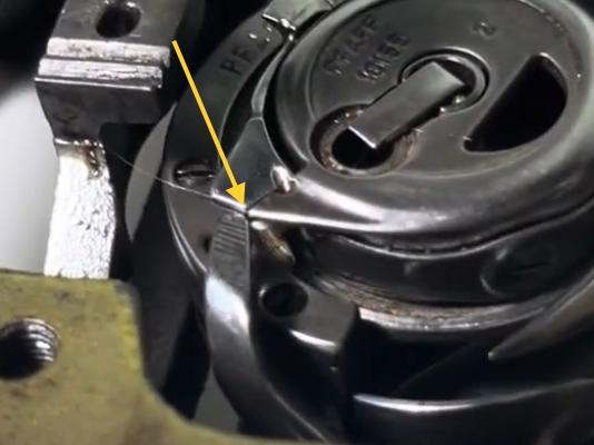
When turning the machine backwards with the bobbin cap on and without the throatplate, the bobbin case opener ends up on the wrong side of the bobbin case “triangle”. Then when you change rotation again it catches on the bobbin cap, causing the bind. That’s not a normal operational situation. There may be other things going on, but that bind in the video is quite obvious. That bind situation would never happen during normal operation of the machine with all parts in place. This video was made on a different machine, but the concepts are the same.
-
The short answer is that there’s nothing wrong with your machine. Don’t turn the machine backwards. Don’t turn the machine much in either direction with the throat plate removed. It’s likely to bind up, especially in reverse because it’s not designed to do that. It’s okay to turn the machine by hand with the throat plate removed while adjusting hook timing, just watch the position of the bobbin case. The tab that’s normally under the throat plate should generally point at the needle when you remove the throat plate, don’t allow it to spin freely. Only turn the machine in the designated direction - meaning the hook will rotate clock-wise. Small adjustments in the reverse direction (counter-clock-wise) are okay, but not a full turn in reverse or more. Bad things will happen.
-
Can you elaborate on that please? That aluminum burr is new to me, I’ve not come across that type of belt in my online searches. A link to a source would be great.
-
This sure looks like an Adler 67 or 167 to me. There should be a type plate on the back of the machine with details and subclass information. In general, they’re very nice, high quality machines made in Germany. We have a bunch topics discussing them here on LW. Do a search on google like this “site:leatherworker.net Adler 67 167” Here’s a leaflet that provides some tech specs for one of the many subclasses: Adler 67-372-373 Brochure.pdf
-
The first thing I would check is to make sure the safety clutch is properly engaged. You may have to remove the bobbin case or the entire hook to make sure no thread is caught under it. A massive jam like you described can leave bits of thread in many wrong places. Tweezers don’t reach in all the place you need to check. It sounds Iike you’re saying the hook catches the needle thread loop but fails to wrap it around the bobbin case. A short video clip of that happening under slow hand-turning power would be super useful (upload video snippet to YouTube and post a link to it here). A few close-up photos is the second best thing.
-
Your machine may bind up because the bobbin case opener is not properly adjusted. This videos explains some of the details around that issue. Your “finger” that’s pulling back on the bobbin case looks different than the one in the video, but the concept is the same. On your machine, you can adjust that finger position front-to-back by loosening the screw that holds the finger in place.
-
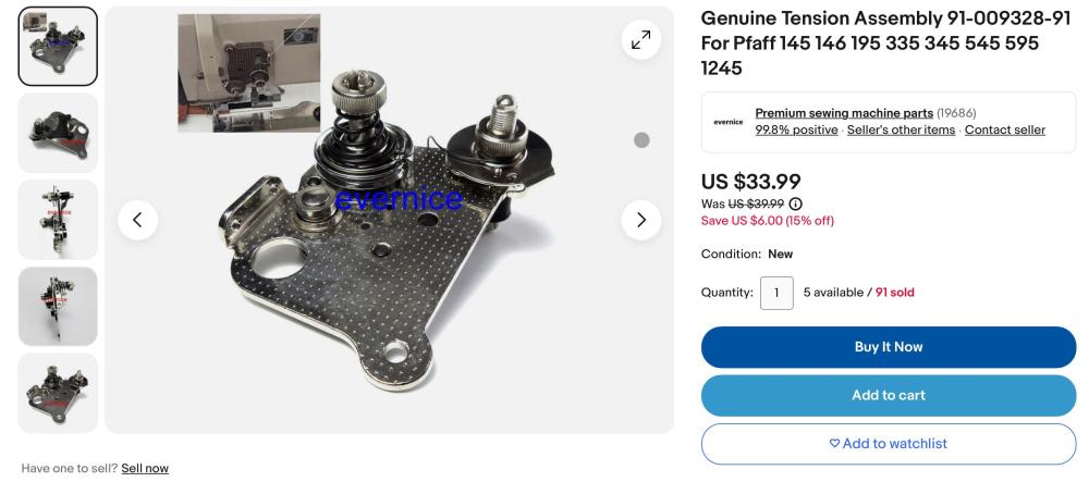
Wow, that machine cleaned up really nicely, congrats! I personally really like that look. No need to contemplate repainting anything, I think. Next I would get a nice, new tension unit, which is readily available on Ebay, and other vendors. One exampleexample :
-

Machine recommendation for best fwd/rev stitch matching
Uwe replied to sojourner999's topic in Leather Sewing Machines
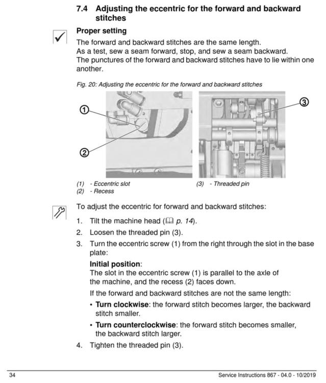
I’d recommend approaching this from a design standpoint. If the machine has a service manual section about adjusting FWD/REV balance, that’s a good sign. That means the engineers actually considered that you might want to adjust that detail and make it easy to do. If the adjustment involves an adjustment screw, that’s going to be a precise adjustment. If you can’t find any instructions in the manuals, then the machine design may not allow (or make it easy) to adjust stitch balance and may not be a good candidate for you. Make sure you track down and read the service manual BEFORE buy a machine. If you can’t find a service manual, I’d say it’s a no-go. Regardless of how precisely you adjust FWD/REV stitch length, it’ll never be a mathematically precise setting in all situations. Factors like material thickness, type, layers, etc. still play a factor. Here’s an example of what to look for. The adjustment section of the Dürkopp Adler M-Type 867 Service Manual shows adjustment steps. It’s one of the best flatbed leather machines I’ve worked with. It might be a candidate worth considering if you can afford it. They run about $5K new. Clones have started to appear as well. -
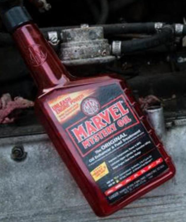
I’d start with a good wipe down with some cleaning oil (I like Marvel Mystery Oil - essentially diesel oil with red dye and perfume) using a soft cloth, a tooth brush, or some other brush with plastic bristles. You may find that much of the rust color wipes off, leaving clean, shiny paint and a dark metal color where paint is missing. It might end up being a pleasing vintage battleship look. The oil then protects the bare metal from rusting again soon. Here’s a pic of the cleaning oil that’s available at most automotive parts stores in the US:
-

Singer 111W151 Presser Foot Tension Adjustment?
Uwe replied to Billfromnc's topic in Leather Sewing Machines
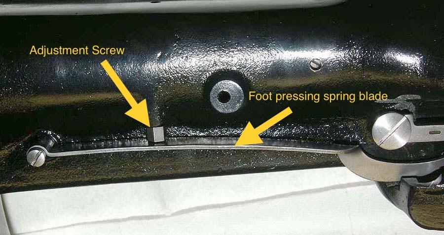
That spring you circled in blue is just there to lift the foot lifter connecting link when you’re sewing, to keep it from bouncing. Your foot pressure spring is a flat blade on the back. The screw above can it can be turned to adjust foot pressure. -
Try Hennigan Engineering & Precision. They make beautiful, high-quality parts for the Adler 205-370: https://heprecision.com/shop/ols/search?keywords=205-370&sortOption=descend_by_match
-

Help me find parts (Adler 204/Cobra Class 7 lookalike)
Uwe replied to PEU's topic in Leather Sewing Machines
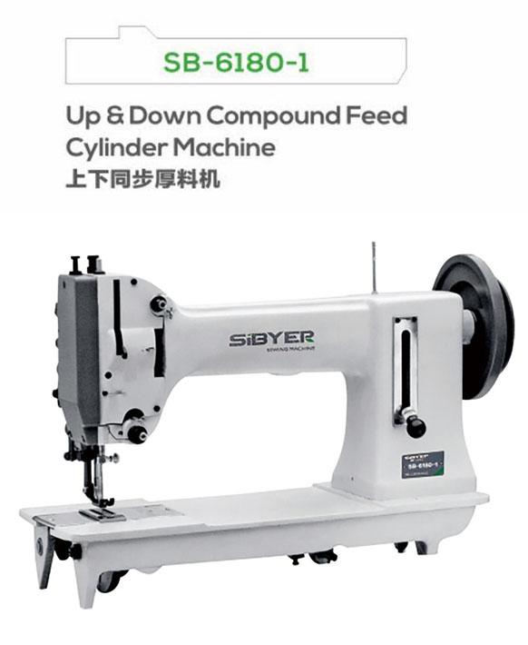
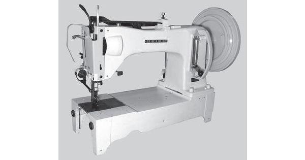
I doubt your Sibyer SB-6180-1 shares many, if any, parts with an Adler 204, Singer 7 class, or Seiko SLH. The resemblance to these machines is just superficial, the details are quite different. I don’t know which machine that Sibyer is based on, sorry. Here’s a pic of the Sibyer SB-6180-1 from the company website: Here’s a picture of a Seiko SLH, which probably weighs twice as much as yours. Pictures often don’t convey a good sense of scale. I think your best (yet slim) hope may be to find a retailer that sells Sibyer machines, and hope they have parts. Or contact Sibyer directly: http://www.sibyer.com , if your Chinese language skills are good. You may be stuck with using the machine as it is, using the parts you have. -

Can a needle positioner be used on a brushed servo motor?
Uwe replied to t20sl's topic in Leather Sewing Machines
“No” is the short answer, I’m afraid. The controller of your servo motor has to support a needle position device, otherwise you can’t use it. If your motor does not have a controller, you’re out of luck in terms of needle position options. Brushed servo motors generally do not have a controller. -

Singer 111w151 problem sewing when hand cranking?
Uwe replied to Billfromnc's topic in Leather Sewing Machines
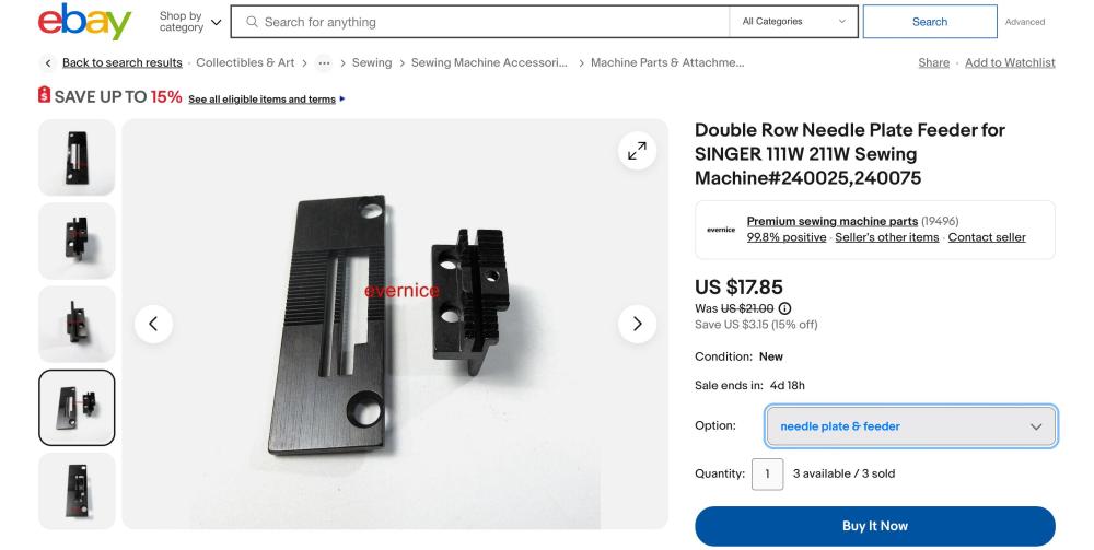
I don’t think the feed dog would cause the problems you’re seeing, but it might be nice to have a new matching set. Here’s one option on Ebay that matches your parts diagram. At $18 they’re cheap enough to just give it a try. https://www.ebay.com/itm/144856325255 -

Singer 111w151 problem sewing when hand cranking?
Uwe replied to Billfromnc's topic in Leather Sewing Machines
It may have to do with the design of the hook. If you stop at precisely the wrong moment and turn back just little bit, the thread may fall under the hook and you’re doomed. Here’s a video that shows that problem: A more detailed discussion of the issue can be found here: -
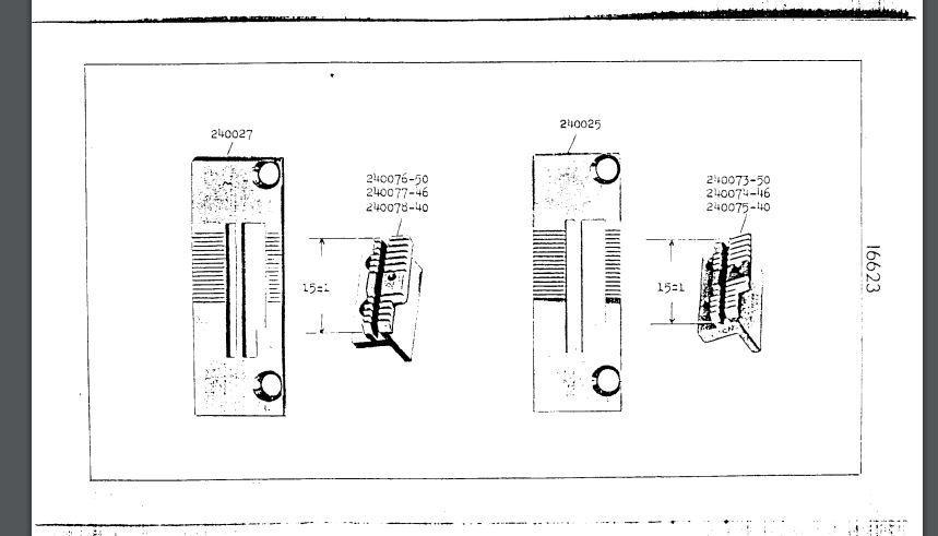
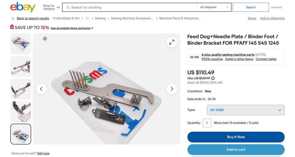
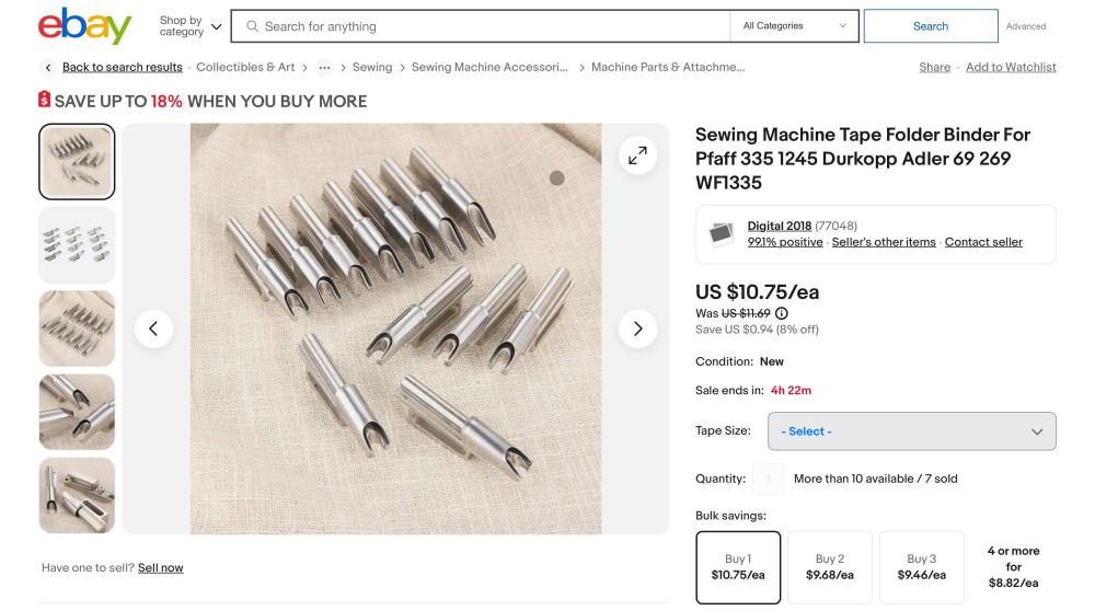
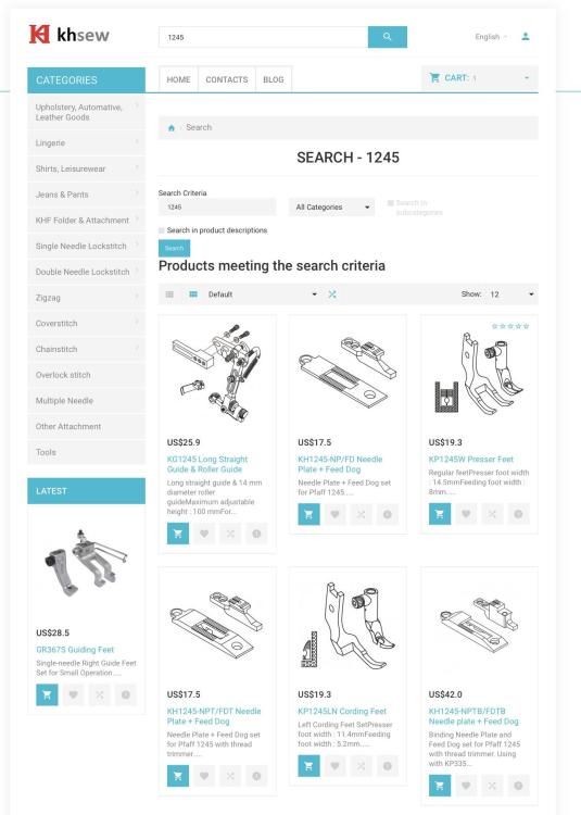
This eBay listing shows everything you need for setting up the machine for binding. At USD $110, it’s not a very big investment. https://www.ebay.com/itm/166181002954 The actual tape folders are kind of generic and not too expensive. Search Ebay for “Tape Folder”.Example: https://www.ebay.com/itm/364562394563 You can also buy high quality parts directly from a manufacturer in Taiwan, called Kwok Hing. Search for “1245”. You have to create an account to see pricing. I’ve ordered from them many times. They also sell tape folders and many other binding parts. https://www.khsew.com/index.php?route=product/search&search=1245
-
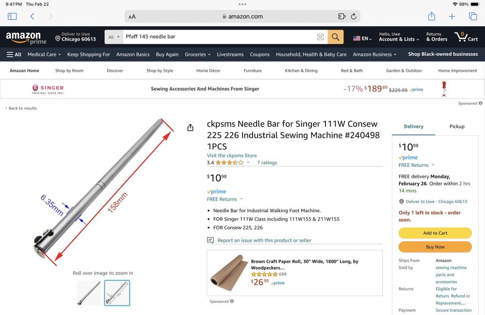
Great, congrats! Please post a link and screen shot to that listing on Amazon. Others may look for the same needle bar in the future. Was it this one? https://www.amazon.com/Needle-Singer-Consew-Industrial-Machine/dp/B077CZCLSG Any details on the installation? Do you have a list of steps, or parts that need be removed to get the needle bar out? There’s precious little documentation available on service tasks for these machines. Anything you can add would help.
-
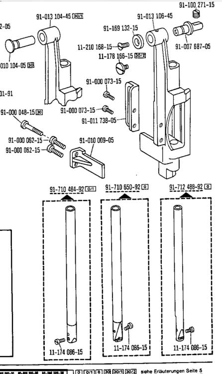
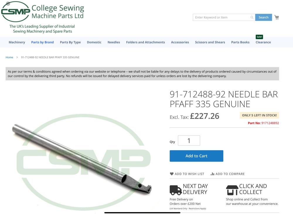
@SingerDadIt’s possible that your old black Pfaff 145 was modified at some point, who knows. That transition from needle bar to needle holder in your photo looks a bit non-OEM to me. To accommodate different-diameter needle bar would require a different needle rocker frame. Perhaps some parts were exchanged in the past from other subclass models. The parts diagram does show two versions of the rocker frame, and three needle bars. I’ve not seen these variations in person, so can’t say if there’s any dimensional variation. The needle bar 97-712488-92 on the right does appear slightly slimmer in the drawing. College Sewing in the UK has that 97-712488-92 needle bar listed as a Pfaff 335 needle bar. It looks very different from what you have on your machine. That OEM Pfaff needle bar is expensive and may not be available in a cheap aftermarket version. If the only offending aspect of your existing needle bar is the missing thread guide hole, I’d seriously consider attaching a small wire loop (silver-solder, glue, spot-weld?) to the tip of your needle bar to make a thread guide.
-
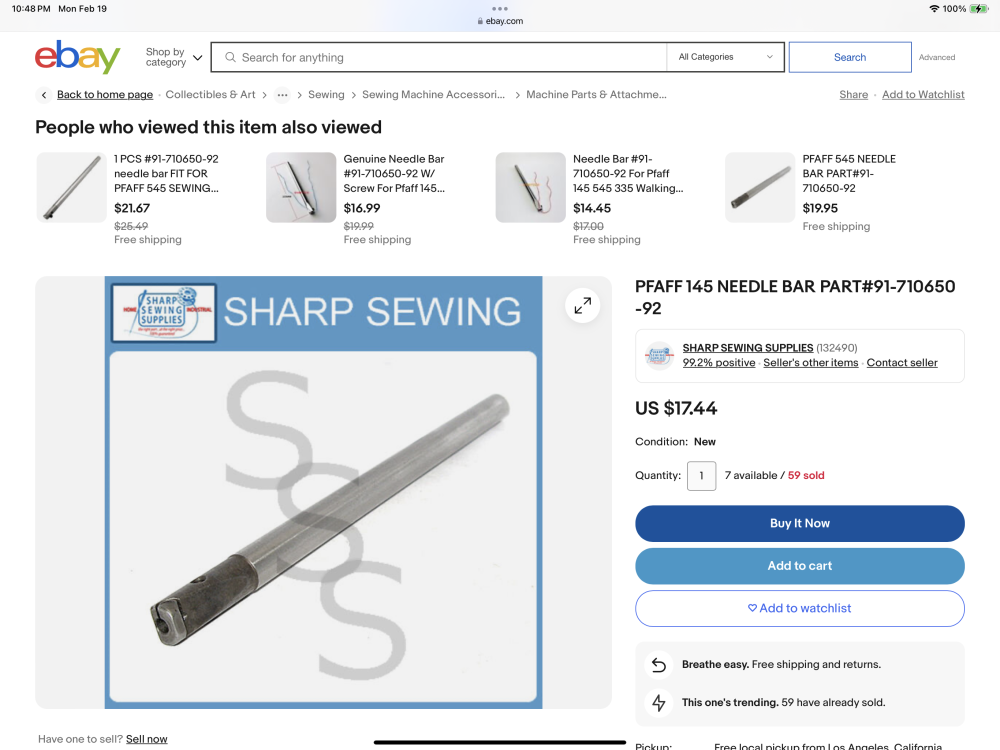
The thread guide does appear to have broken off on your needle bar. Buy a replacement part based on part number, not based on some measured diameter. Ebay is a good place to research part numbers quickly, if you’re not into examining parts diagrams (https://www.diamondneedle.com/documents/Pfaff Parts Manual/145_545.pdf). Just search eBay for “Pfaff 145 needle bar” and multiple vendors will have offerings with the Pfaff part number in the title. In this case : 91-710650-92. The parts list shows a few variations of the needle bar, but I think this is the one you’re looking for. They all should have the same diameter. Here’s one example from a US based vendor: https://www.ebay.com/itm/122464240704 Screen shot: If you want to get an OEM replacement part, you can order it directly from Pfaff/DAP in Atlanta Georgia (https://www.dapamerica.com/products-and-services/#) . Call their parts department and give them the part number. It’ll cost more than the cheap copies available on Ebay but may well be worth it. Replacing the needle bar may be a bit involved. Your existing needle bar will need come out the bottom, which means you’ll potentially have to remove everything that’s in the way (throat plate, feed dog, hook, etc.) I’m not sure it’s essential to replace the needle bar just for the thread guide hole. You can make/hack some thread guide out of a piece of wire and it’ll probably work just fine. Some of the other needle bars for this series don’t have a thread guide hole at all.
-
Debugging friction is very hard to do sitting in front of the machine, let an alone remotely. Lift the feet up, so you’re not lifting feet against spring pressure when you’re turning the hand wheel. That spring pressure can feel like a tight spot. Make sure things are well oiled and clean. Old, dried oil residue can cause friction in unexpected places. In my hook timing video I show one step to align an eccentric bushing (at the 8:50 mark.) I had noticed this because it was suddenly causing a tight spot after I made an adjustment because the part was no longer properly aligned. I’m not saying your machine has this specific issue, but to show that a tiny adjustment can introduce a point of friction. When I work on a machine I’m generally very methodical, changing one thing at a time and checking if I’m introducing a tight spot. Here’s a link to that hook timing video, for the benefit of others reading this topic:
-
Neither of the two Puritan catalogs I have (Puritan-Catalog-Manual-Parts-older.pdf Puritan-Catalog-Manual-Parts-newer.pdf) show this model. The Puritan website (http://www.puritanindustries.net) existed in 2015 but appears to have been abandoned. The company itself may still exist, but they’re not making it easy to find or contact them. Online searches only reveal a few obscure (and likely obsolete) references when searching for Puritan Industries. Most of what I know about Puritan is based on my Puritan saga in 2015 (nine years ago!) chronicled in this topic: Bottom line from my perspective is that I’ve given up trying to make my own Puritan work. My machine had mismatched parts, and making them match was cost prohibitive in 2015 and may be downright impossible now. @DeKing best of luck with your machine. My advice would be: Don’t get too invested and prepare for disappointment.
-

[ Speed Problem ] Durkop Adller 867 - Classic
Uwe replied to ZlaPatofna's topic in Leather Sewing Machines
Maybe the motors don’t have the same size pulley installed? There may be other parameters that control motor speed. Perhaps one machine is actually sewing slower than the other because of some other parameter limiting speed. You assume the slower machine runs at 2400rpm - maybe it’s the faster one actually runs at 2400rpm. You’d have to compare all the speed related parameters between the two machines to make sure they’re set identical. -
Also keep in mind that with this type of machine, you have to hold the top and bottom thread for the first few stitches to avoid a bird’s nest. If the hook catches the loop, you can’t be too far off. Here’s a picture of how to hold the thread when you start sewing: Here’s how to check the safety clutch and reset it on the Pfaff 545. Here’s how to install the bobbin using the bobbin cap:
-
There are lots of topics around the Cowboy 4500 here on LW. It’s a very capable machine and very popular here in the US. It’s a copy of the Juki TSC-441, which is still in production. Essentially the same specs as the Adler 205. The Adler has some technically superior details (like cam-driven foot lift motion), but you may not notice the difference in your work. At $800, it too would be bargain- if it’s in good shape. They sell for around $3,000 new here in the US.
-

Is there a way to change singer 111w knee lifter to foot pedal?
Uwe replied to SingerDad's topic in Leather Sewing Machines
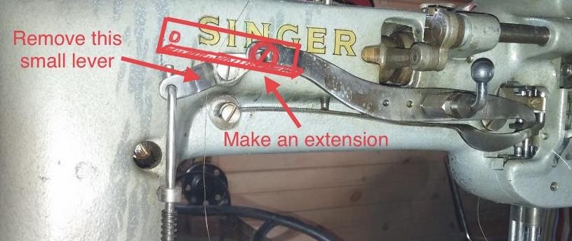
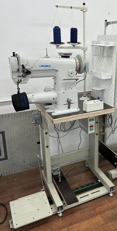
It’s possible to do this. I had a machine once that had been converted, but I don’t have pictures, sorry. Essentially you have to remove the small pivoting lever and extend the existing long foot lift lever with a suitable piece of angle stock or C-channel that hooks under the lever for, well, leverage. You can use the existing hole/slot in the lift lever to attach the extension with a bolt&nut. Then you can run a small chain or flexible metal wire from the end of the lever extension to a pedal you step on. Here’s a sketch of the concept: Depending on your table configuration you can use an existing pedal, or you can make one from a hinge and a piece of wood like this foot lift pedal on the right.


