

Uwe
-
Posts
2,221 -
Joined
-
Last visited
Content Type
Profiles
Forums
Events
Blogs
Gallery
Store
Everything posted by Uwe
-
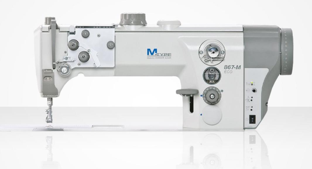
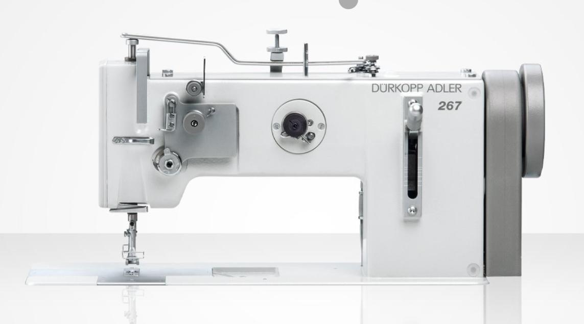
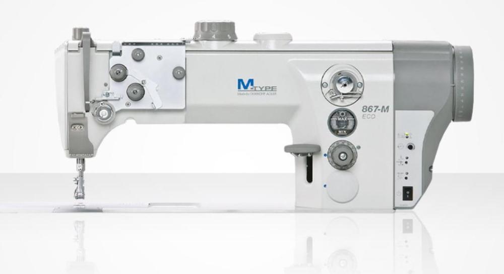
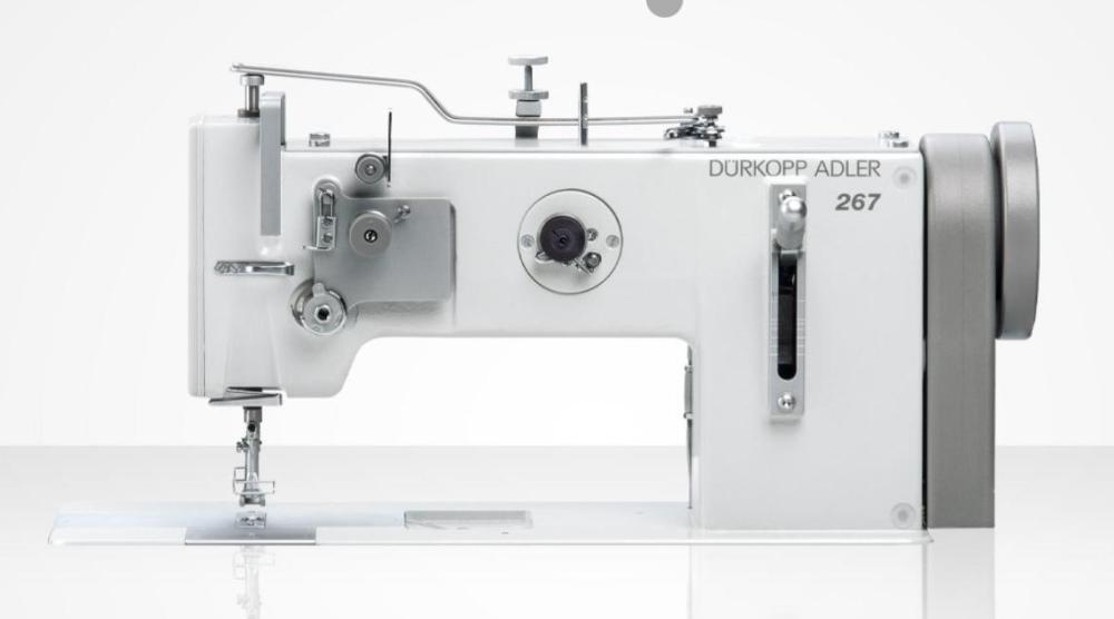
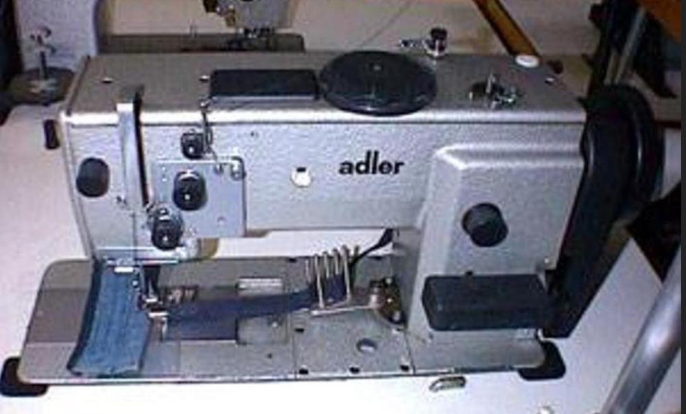
Yes, the Durkopp Adler 867 M-Type is the current design iteration: https://www.duerkopp-adler.com/products/industrial-sewing-machines/industrial-applications/hkl-site-m-types/m-type/#panel0 The Durkopp Adler 267 is a vintage design from the 80’s that Durkopp Adler still sells new: https://www.duerkopp-adler.com/products/industrial-sewing-machines/industrial-applications/basic-machines/267 This is a very nice vintage design. The Durkopp Adler 667 and 867 are modern M-Type designs. The M-type series represents a major design change and they have little in common with the older models. There also were 467 and 747 models, both entirely different designs from the 267 or modern M-type. I would not recommend these models - they work great but a tricky to adjust and repair. It gets confusing because the 667 M-Type came out well after the 767, I don’t know why. I think they backed up their numbering scheme when they launched the M-Type class of machines. And the 967 H-Type is a total monster of a super heavy duty machine. If you can afford a new OEM machine, I’d recommend the M-Type 867-M. They’re amazing machines and it’s what I would buy again if I needed a new OEM upholstery class flatbed machine. I’ve owned one for a while, later sold it, and immediately regretted selling it. I’ve attended a factory service workshop on this model - it’s easy to adjust and the documentation is really, really good. A few pics just to illustrate the various models: Durkopp Adler 267: Durkopp Adler 467 and 767: Durkopp Adler 867 M-Type:
-
I’m glad you got it figured out! I wonder if that washer is in the parts diagram, or if it was added later for some reason. There may be difference between the older Adler and the newer Durkopp Adler versions of the 69-373. The casting is not quite the same. I don’t have any documentation for the old, pre-Durkopp merger, Adler 69-373. The one I had was the later Durkopp Adler 69-373.
-
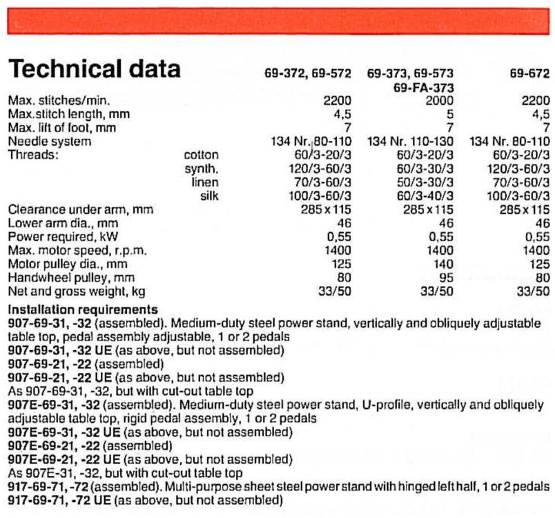
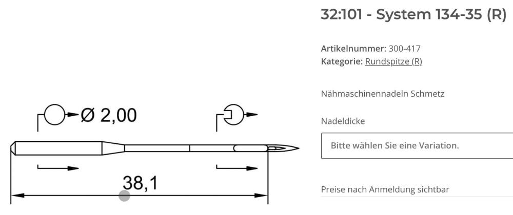
The Durkopp Adler 69-373 uses a System 134 needle, not System 134-35. That may not be the cause of your issue, but it’s generally best to use the correct needle system. The 134-35 needle is 4.2mm longer than the 134. The size of the needle matters, too. The 69-373 is designed to use size NM 110-130. A thicker needle gets closer to the hook just due to the diameter of the needle. Try a System 134, size NM130 needle and report back. A few close-up photos of your hook area would be helpful, or even a small video snippet (via YouTube) of the hook touching the needle. The Durkopp Adler 69 service manual ( Durkopp Adler 69-373 Service Instructions.pdf ) is a good reference for making adjustments.
-
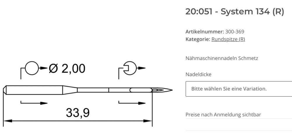
The Adler 269 is a very nice design and generally a great machine. Don’t let the startup issues get you down. There may be multiple things going on: First, your hook-to-needle timing may be off a little. Forward is more forgiving than reverse. In my experience, if machine sews well in reverse then it almost always also sews well forward. The opposite is not true. Carefully timing the hook and checking reverse in the process should help with that problem. Not only does the needle need to pick up the thread reliably, the hook also needs to let go of the thread when the thread take-up lever start pulling up. Sometimes forward is fine, and in reverse all hell breaks loose , the thread snags on the hook tab, or the hook gib doesn’t let go of the thread soon enough - all of these things cause loops on the bottom, A small amount of retarding or advancing hook timing should resolve that. Second, it looks like your feed timing/balancing may be off, the reverse stitch length should match forward. If your machine has adjustable hard stops at the top and/or bottom of the reverse lever slot, make sure they’re are not causing the problem with short reverse stitches. The manual doesn’t specifically address stitch balance, but in general, if you have maximum stitch length dialed in and the needle is in hook timing position, flipping the reverse lever up and down should NOT move the needle. Small adjustments of the feed eccentric on the top shaft should correct any unwanted movement. The Adler 269 service manual ( Durkopp_Adler_269_instructions_for_service.pdf ) should apply to your machine, go through it in sequence verify the various “rules” or reference positions it describes. Make adjustments if needed. Normally the dealer does this, they may have missed a few steps.
-
Getting the knot to be consistently in the middle of the material is a delicate balancing act. Both top and bottom tension have to be close and consistent. There are lots of ways to mess with the consistency part. Anything that increases or decrease either top or bottom tension momentarily may cause knots to show on the top or bottom. Since the up/down pattern looks to be about the length of one bobbing winding, that’s where I’d look first. Sources of momentary tension changes (not in any particular order): 1. Spool unwinds unevenly, perhaps due to a sock, or lack thereof 2. Hole on arm above spool is not directly above the spool, causing non-symmetrical unwinding 3. The thread is springy and wants to coil around something 4. Poorly wound bobbin (a crowd favorite!), perhaps try a pre-wound bobbin as reference? 5. Dangling thread end under the bobbin catches something on every turn 6. Bobbin itself has a burr that catches on something with every turn 7. Leather is a natural material and not consistently thick/hard/scarred/lumpy, etc. 8. Needle tip geometry may cause variations in the exit hole on the bottom, changing how hard it is to pull the knot into the material 9. Needle size is incorrect, increasing the odds of problems 10. Lumpy thread 11. Neutrinos zipping through the earth Pull slowly on the bobbin thread and feel for tension changes as the bobbin unwinds. If it feels uneven, that’s a problem. Same for the top thread, remove from eye of the needle and pull slowly. If it feels uneven, that’s a problem.
-
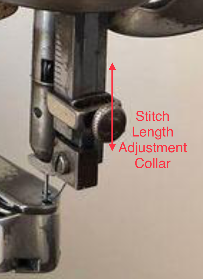
Yes, you can adjust the stitch length by sliding the little rectangular collar above the presser foot up or down. It provides the longest stitch length when the bracket is at the bottom. As for leaving marks, the presser foot top feed is the only thing that’s moving the material, so it’s needs to have grip either by means of the teeth, or some other, smooth-ish friction. A bit of heat shrink typing might do the trick. A totally smooth, slick foot will not leave marks, but it also won’t transport the material. Some people have experimented with filling the teeth with baking soda + super glue, and dipping the foot in some type of grit, essentially giving a sandpaper type surface. This, in theory, would provide good traction without leaving visible marks. Scraping some grit off coarse sandpaper would probably work just as well. The feet are relatively cheap, just buy some and experiment. When making custom belts from polyurethane belt stock by melting the tips on a hot box cutter blade, I noticed that the melted stuff sticks really well to the box cutter blade. I’d be tempted to try melting a small piece of PU belt in a tiny metal cup with a torch lighter and then dipping the foot into it. Might give a nice, soft-ish, sticky coating. Maybe dip the still-melty material in some grit. Eight years ago somebody described having figured how to attach diamond grit to a smooth presser foot, similar to making diamond coated cutting blades. It’s an electroplating process that’s perhaps not accessible to the average at-home tinkerer. I bought some of that special diamond grit years ago, but never got around to trying it out.

-
I have the service manual so I’ll attach it here: Adler-220-Service-Manual.pdf Yes, the Adler 220 Service Manual will be important. Just go through all the adjustment in sequence, and you should be in much better shape.
-
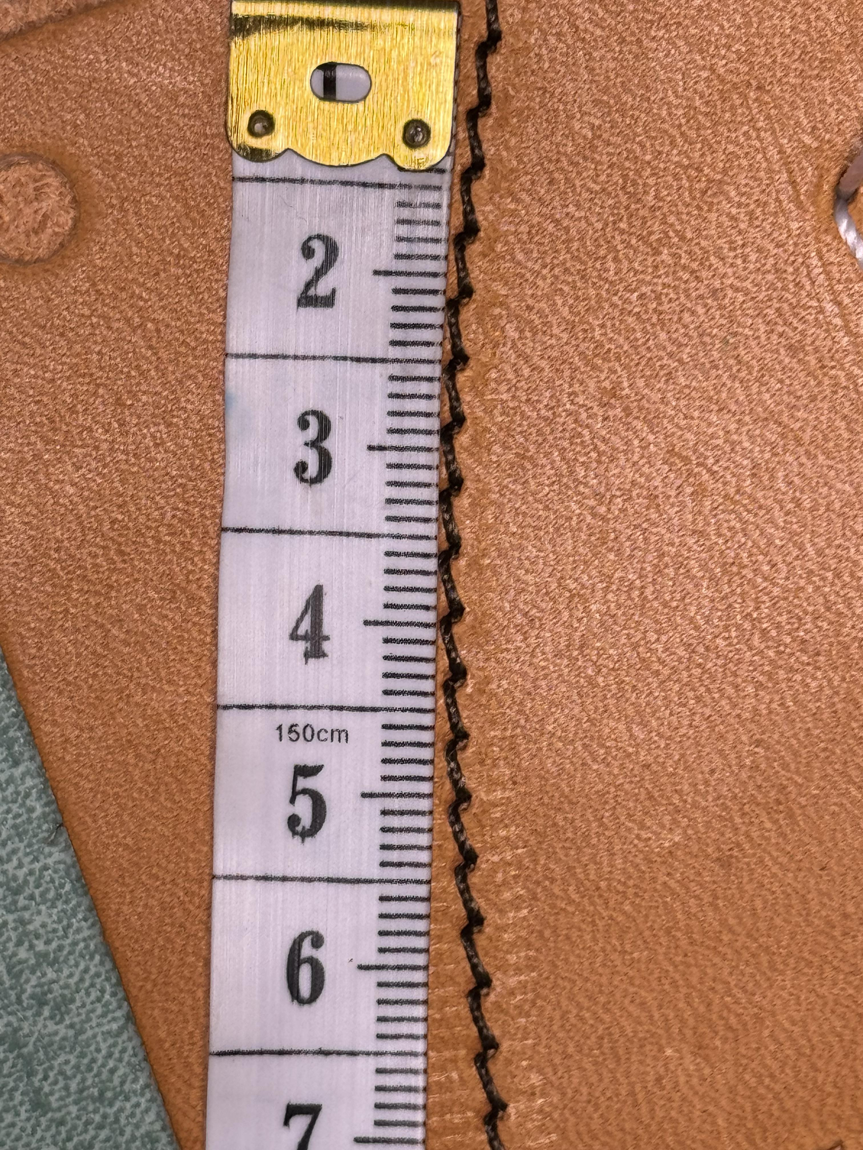
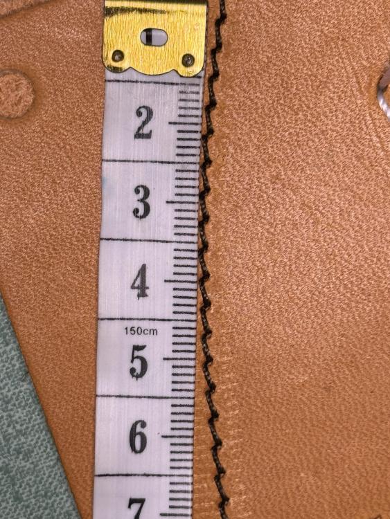
I checked my Adler 30-1 and got about 3.5mm max per stitch. There are different size needles available for this machine. CAD$500 is a reasonable price for an original Adler. You can probably get that money back when it comes time to sell it, making the machine essentially free for the time you use it - gently. You can add a servo motor, but you don’t have to - it’s fully functional using all-manual mode.
-
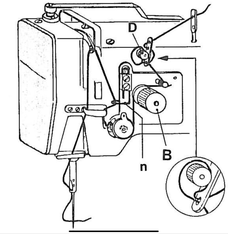
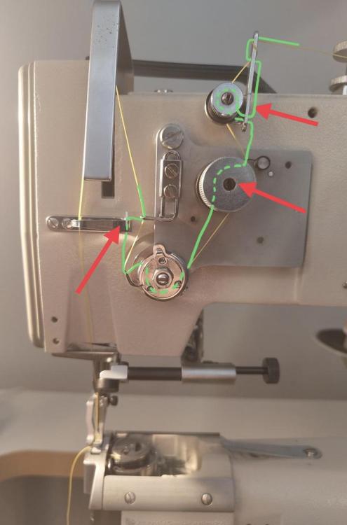
Yes, the photo sure looks like the top thread path is not quite right. Pre-tension loop (D) is not right, going around the main tension discs (B) in the wrong direction, not pulled between main tension discs (B), not going up through the thread guide after check spring. Here’s the threading diagram from the Durkopp Adler 268 manual (same top threading as 269):
-
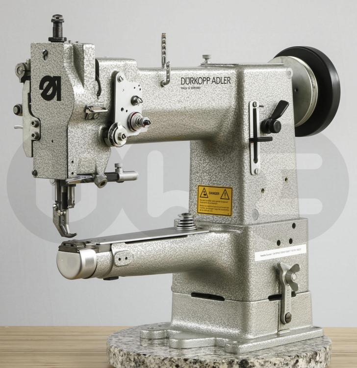
That machine looks like it’s in super nice condition! The only thing missing I can see are the thread tension discs on the front, not essential and easy to fix.The front mounted hand wheel is a nice touch. Hooks and bobbins are readily available and cheap. In general, patchers are not well suited for making shoes from scratch. They may be perfect for particular steps in the shoe making process, but they’re general not used to make entire shoes from scratch. They’re great for repairing shoes, bags, backpacks, etc. But then again, it depends on the type of shoe you’re trying to make. A friend if mine loves her patcher for making very specialized shoes/boots for her cirque du soleil type trapeze act, from scratch.Those boots are combination of soft ballet shoes and lace-up burlesque boots. The main issue with these type of machines is that the feet have very aggressive teeth to move the material and they are VERY likely to leave marks on the leather. That’s not a problem if you’re dangling from a trapeze fifty feet away, but it is a problem if you inspect the boots up close. It’s also not a problem if you’re sewing fabric or webbing straps. As for stitch length, I’m guessing it maxes out around 3-4mm, depending on material and traction. I put an Adler 30-1 at my maker space and can make some test stitches later today to verify.
-
If your hand-wheel is attached to the front of the machine, then the correct way to operate machine manually is indeed to turn the hand wheel clock-wise.
-

Help with thread wrapping around bobbin case.
Uwe replied to cynthiab's topic in Leather Sewing Machines
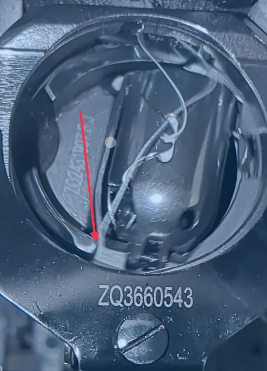
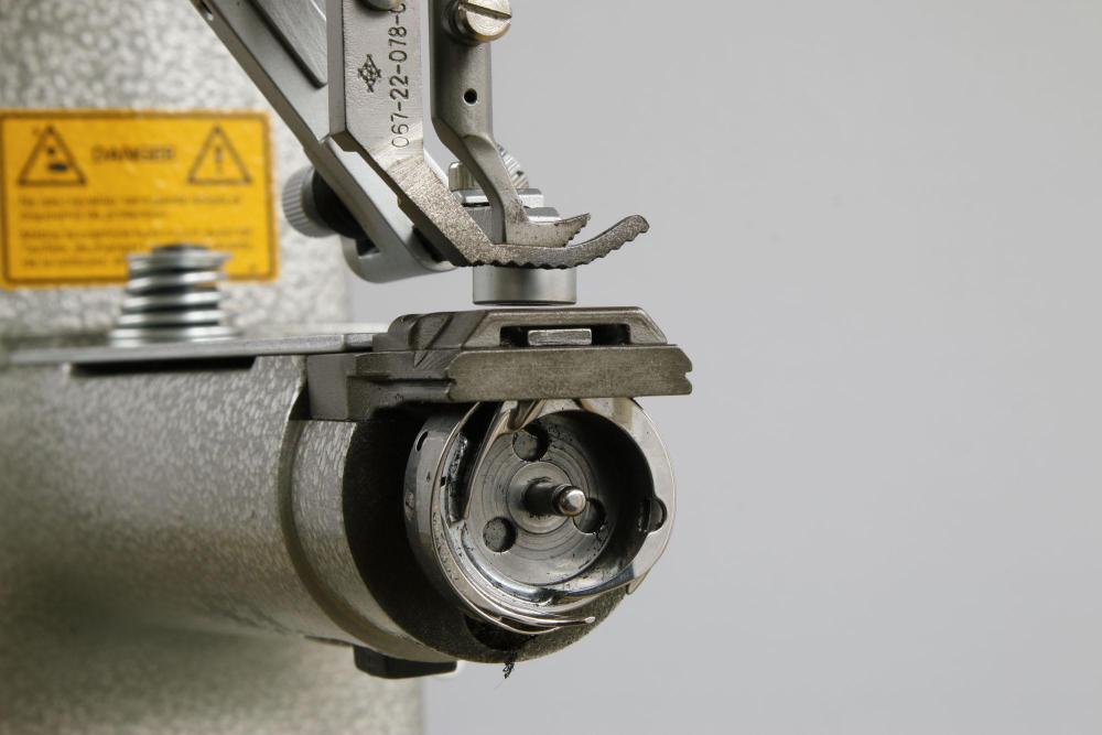
With this type of hook, you may also experience the thread falling off and getting caught under the hook if you stop at precisely the wrong moment, turning or not. That’s what your multi-thread pictures actually looks like. This topic from 2016 goes into details and possible fixes: -
Pfaff 335 Sewing in Reverse, please help
Uwe replied to Hickenbottom's topic in Leather Sewing Machines
It’s not clear to me whether you have the vintage casting or modern casting version of the Pfaff 335. The service manual (https://www.manualslib.com/manual/1091134/Pfaff-335.html?page=11#manual) for the modern casting Pfaff 335 has this adjustment procedure for the feed motion: What does your machine do at max stitch length and the needle position at BDC, when you move the reverse lever up and down? That eccentric ring may be off by 180˚ on your machine. A few well lit pictures of your machine’s insides would help, just to add arrows and point to things. A short video clip of the machine misbehaving would really help as well (upload to YouTube and post the link here)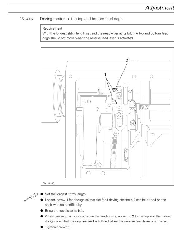
-
That QR code on the side of the controller box is very likely a link to the manual. I doubt the torque is adjustable. If the parameter doesn’t exist in the manual that came with the motor, then it probably just doesn’t exist.
-
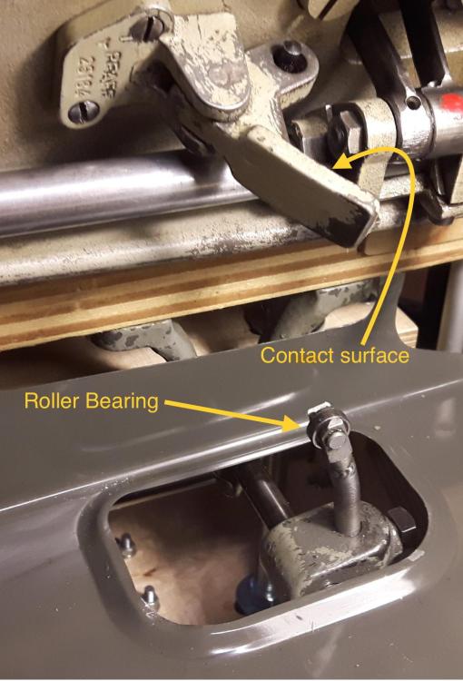
One more picture to complete the foot lift mechanism. Your labeling of the first picture is correct. The second picture shows the part that actually makes contact with the lift mechanism on the underside of the machine. Block #3 is just there to keep the shaft from sliding axially towards the back. My third picture shows the foot lift details when you tilt back the machine. The roller bearing is on the original Pfaff foot lift, it’s not clear if your machine has the same. If your machine doesn’t have the roller bearing, it’s not the end of the world, just a less smooth movement. When you actuate the foot lift mechanism via the knee pad, the roller bearing presses against the contact surface to lift the foot. There are two considerations here: 1. The distance between the roller bearing and the contact surface at neutral position (not pressing agains the knee pad) determines how much play your knee pad has before it starts lifting the foot. 2. When you lower the machine back down after tilting it back, you have to make sure the roller bearing ends up to the right of the part with the contact surface. If the bearing ends up to left of the part, then the roller bearing will not push against the contact surface and the knee lift will not work at all. You may have to push the knee pad to the left as you lower the machine to achieve the correct operating position. The goal of your adjust is to get the roller bearing very close to the contact surface while the knee pad is in a good neutral position. You can either adjust the knee pad at the front , or you can adjust the roller bearing part in the back. It’s all relative, and connected.
-
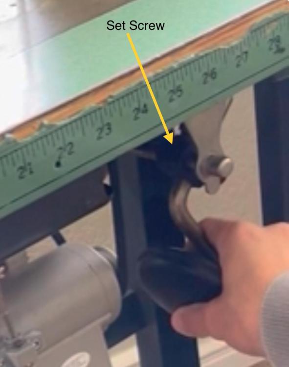
I’d oil the knee lift bits, they look like they have friction without touching anything. Then adjust the knee pad leg bar position so it’s very close to making contact when it’s in the normal, down position. Currently there’s too much free motion before it touches the lifting mechanism. There’s a block that connects the angled pad leg bar to the horizontal shaft. There are two set screws, the one on the bottom fixes the pad leg bar to the block, and the one on top other fixes the block on the horizontal shaft. You can adjust the position of that block (and thus the pad leg) on the shaft (sliding and rotating.) Rotate the pad leg bar clock-wise on the shaft until it has just a little bit of free motion in the down position. The arrow in the picture points to the location of the set screw you need loosen to make the adjustment. Hold the horizontal bar with your finger or pliers close to the contact position, then rotate the pad leg bar so the part with the pad is vertical. You may wish you had three hands to do this.
-
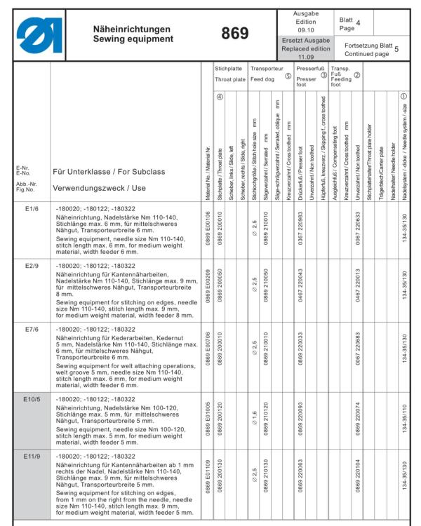
It looks like some feed dogs have not changed since the 67/69 model, but the needle plates are new for the 869 model. In general, if two parts have the same part number in different parts lists (e.g. in the 69 parts list AND the 869 parts list) then the parts themselves are identical and interchangeable. When you look at the parts list, many part numbers will show on which model the part was first introduced (and hasn’t changed since.) A part number starting with 0067 was fist used on the 67, a part number starting with 0367 was first used on the 367, etc. Part numbers starting with 9 are not model specific. The Durkopp Adler 869 parts list (https://www.duerkopp-adler.com/fileadmin/dag/Media/Downloads/869/TL_869.pdf) shows available sewing gauge combinations at the end. Some feed dog parts numbers start with 0067 (or 0467), the throat plate numbers all start with 0867. That means the fed dogs will likely fit all models 69 through 869, but the throat plates will likely only fit the 869. Here’s a screen shot of one of the pages from the manual:
-
It would be nice to share these upgrades, modifications, and tips for all to see.
-
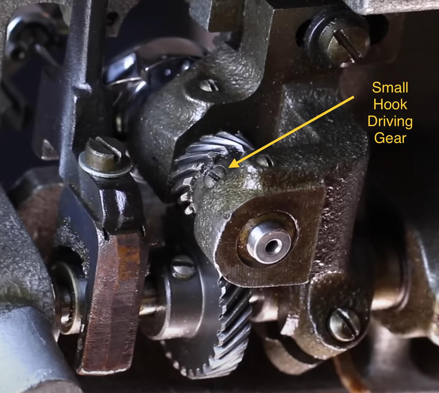
That slow speed sewing looks very nice! As for your bobbin case opener, there’s a few possibilities as to why it’s wobbly (in order of likelyhood): 1. The hook may not be seated all the way down, allowing the bobbin case opener disc to move vertically a little. 2. The parts may be worn and have too much play 3. Some parts may be incorrect The wobbliness may actually be fine as long as the finger reliably pulls back the bobbin case to the correct position (tab in center of the cutout under throat plate) Seating the hook properly is a relative easy thing to do. The small hook driving gear holds the hook in place rotationally and vertically. If you loosen both set screws on the gear just a little bit, you can move the hook vertically. Make sure the hook is seated all the way down to minimize vertical movement of the opener mechanism. Sometimes the hook gets forced up by thread getting caught under the hook. Even if you remove the thread, the hook may still be riding a little too high afterwards, allowing play in the opener mechanism. You may have to re-time the hook or adjust the needle bar position if the vertical adjustment of the hook was significant.

-
Fudging stitch length @ a border/corner: Cobra class 4
Uwe replied to DieselTech's topic in Leather Sewing Machines
I would turn the hand wheel to bring the tip of the needle very close to the material without the inner foot touching the material. Then move the stitch length lever until it points exactly where you want the stitch to go and make the stitch. -
Help me find parts (Adler 204/Cobra Class 7 lookalike)
Uwe replied to PEU's topic in Leather Sewing Machines
@PEU Brilliant, love it! -
Help me find parts (Adler 204/Cobra Class 7 lookalike)
Uwe replied to PEU's topic in Leather Sewing Machines
Very cool, congrats! How did you embed the metal rod in the part? -
Trouble with new industrial pattern machine
Uwe replied to JustinLohmann's topic in Leather Sewing Machines
Yup, it sure looks like there’s a burr on the hook or driver that cuts the thread. I’d remove and inspect the hook. Polish any sharp edges smooth or just replace the hook with a new one. It takes just a tiny burr to act like a cutting knife.
-
-
Thanks for that clarification, I appreciate it!