

Uwe
-
Posts
2,221 -
Joined
-
Last visited
Content Type
Profiles
Forums
Events
Blogs
Gallery
Store
Everything posted by Uwe
-
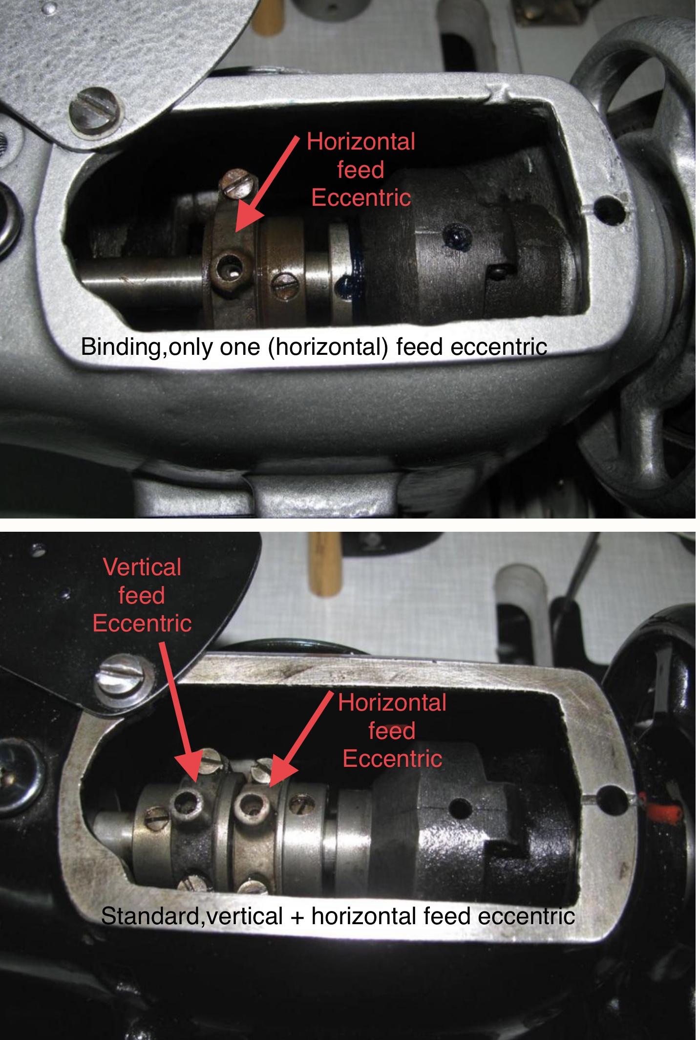
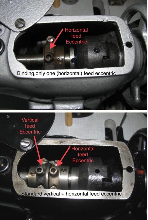
Thanks for moving the topic to the public forum @barclay The feed motion eccentrics on your machine should look like this: One eccentric (top picture) if your machine has no “P” in the model code, or two eccentrics if it has a “P” in the model code. To adjust the feed eccentric: 1. Bring the machine into the “needle 0.6mm above BDC” position. 2. Loosen both set screws that clamp the eccentric to the shaft (NOT the two screws that connect the rod to the eccentric). One set screw should accessible from top, the other from the rear access port. 3. Flip the lever up and down and rotate the eccentric on the shaft until there is no noticeable feed movement. It should be a subtle adjustment in your case. Normally one set screw is vertically aligned with the shaft when the eccentric is in the neutral position. 4. Tighten the top set screw first (if it’s at the bottom you’re off by 180˚), then the other set screw (it should be accessible from the back of the machine) If you have the vertical feed eccentric, adjust the horizontal feed eccentric first, then adjust the vertical eccentric so that the feed dog rises at the very front, just before it starts moving towards the back. By the way, you have to click on the user on the pop-up list that shows up as you type the user handle in order to properly tag a user and send notifications, like this: The user handle then becomes highlighted and activated like this:


-
To adjust feed dog height, loosen these two screws (red arrows) and rotate the clamp on the shaft. It’ll be a very small adjustment. Thanks for all the other photos, by the way! They will be useful before too long.

-
This might make things a bit simpler to investigate, since there are fewer moving parts involved in the feed mechanism. Here’s what I would do next: Dial in the maximum stitch length and turn the hand wheel until the feed dog is in the very front position. Keep flipping the reverse lever up and down. Observe and inspect everything that moves anywhere in the machine. Oil every spot that has two surfaces touching and moving against each other. That throat plate and feed dog combo is likely for a standard feed machine and may not be correct for your variant. Parts sometimes fit, but don’t really work. The binding feed dog and throat plate set looks very different and may have different clearances. Please post more pictures of the head, internals and rear of your machine, with cover plates removed. I spend entirely too much time trying to find a suitable picture online just to add an arrow.
-
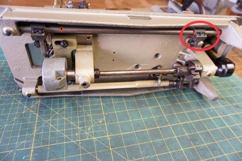
Your machine may be a binding machine - it appears to be missing the linkage that drives the vertical feed dog moment. Here’s a picture of a standard Pfaff 145 with the clamping block installed that normally connects a rod to the vertical feed drive eccentric on the upper shaft (red circle) Your machine instead has a clamp installed that fixes the position of the vertical feed drive shaft (red circle): I annotated a picture by @Constabularyfrom an earlier thread that shows the difference in the feed drive eccentrics on the top shaft between standard and binding versions of the Pfaff 145. This is the original thread:

-

Questions about a Pfaff 545-H3-6/01 CLPMN
Uwe replied to Elcheatobandito's topic in Leather Sewing Machines
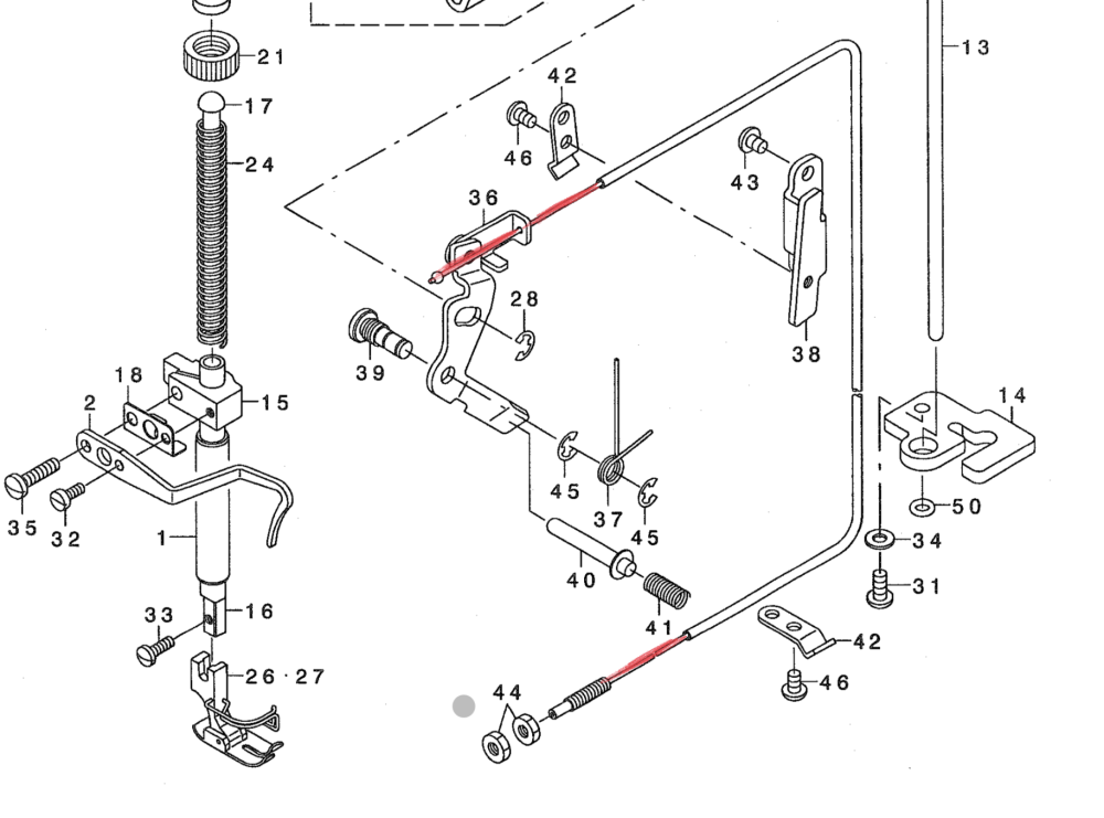
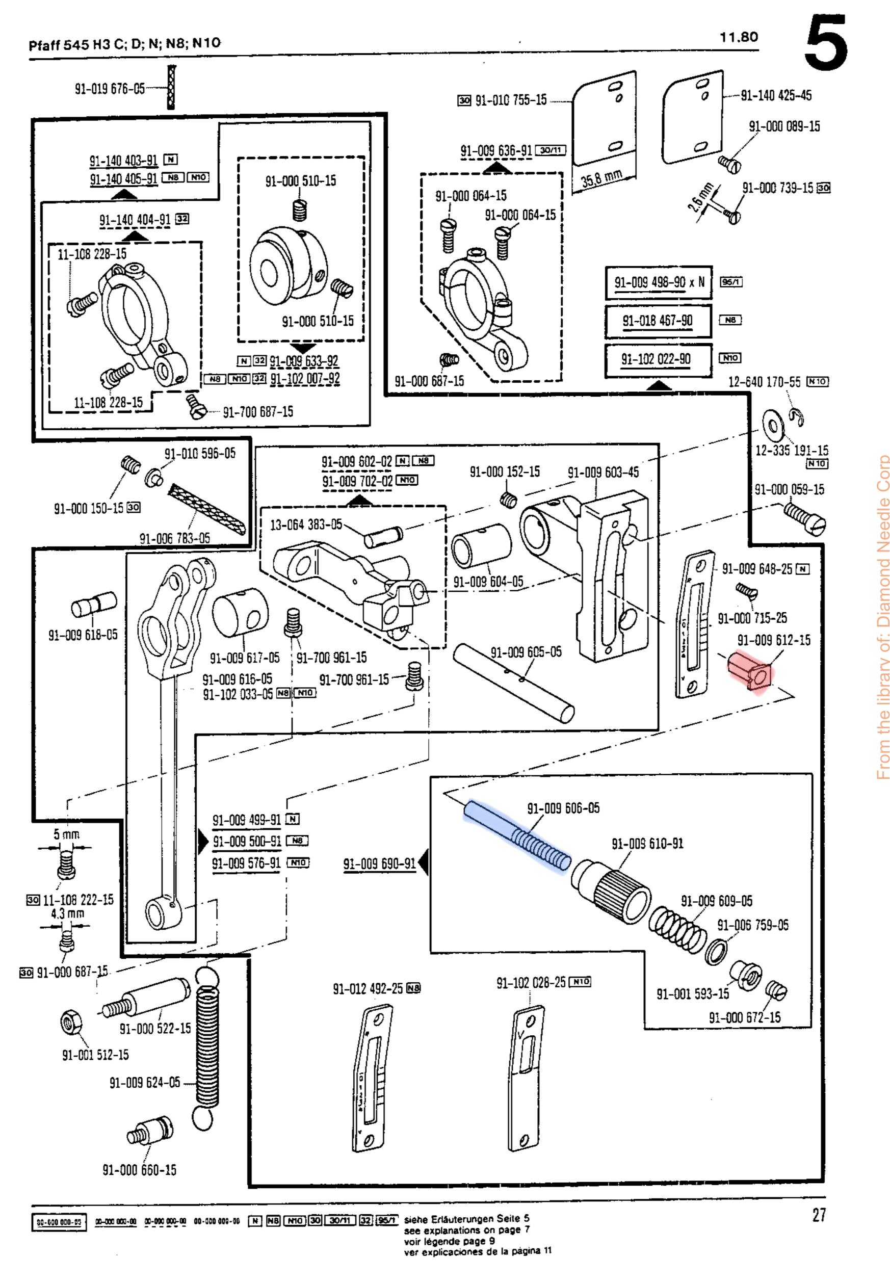
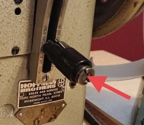
Your threaded stud may not be seated all the way in, making the thumb screw thread bottom out too early. The bits inside the thumbscrew (red arrow) are not supposed to stick out that far. The Pfaff 145/545 parts (https://www.diamondneedle.com/documents/Pfaff Parts Manual/145_545.pdf) manual shows how the parts of the lever fit together. The threaded rod (blue) in the screen shot below is the part that may stick out too far. That threaded rod is probably held in place by a set screw. Getting to that set screw may not be easy. The little bushing (red) sometimes breaks (if plastic) or goes missing altogether. If you remove the thumbscrew, be mindful that there’s a spring in the assembly. Things may pop out unexpectedly.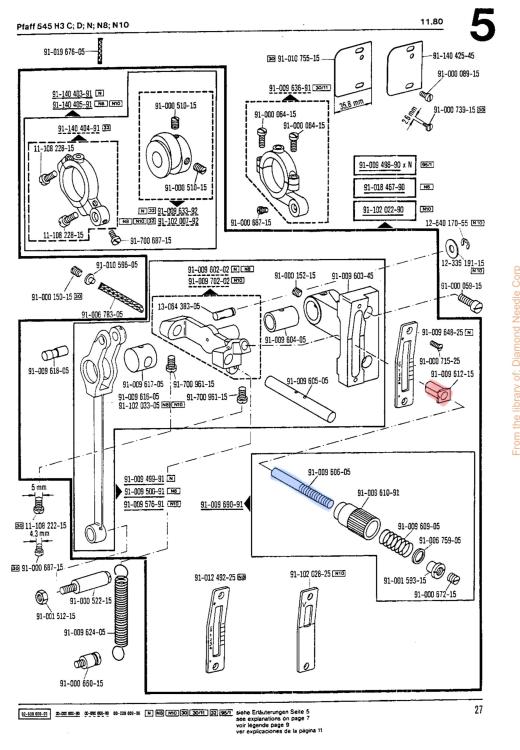
-
I have a feeling this is an adjustment issue (most likely in the feed mechanism) or a missing or incorrect part (for example, the spring for the reverse lever is broken or missing) Top thread path in your picture looks good. Try this: Dial in maximum stitch length and turn the hand wheel until the feed dog is in the very front. It should NOT touch the front of the throat plate opening. Flipping the reverse lever up and down shows the full range of motion of the feed dog - it should not touch the throat opening at either end. If it does, that’s a problem.Ideally the movement of the feed dog is centered in the throat plate opening. Remove the motor belt and lift the feet with the manual lever. Turn over the hand wheel by hand and feel for resistance. There should be almost no resistance when turning the wheel, and any resistance should be very even during the entire stitch cycle. On the Pfaffs I had, giving the hand wheel a good spin would keep the machine spinning for two or three cycles before it stopped due to friction. If you feel strong resistance or a “tight spot” at any point during the cycle then that indicates a problem somewhere in the mechanism. Sometimes, when the feed motion mechanism touches something it shouldn’t, the reverse lever start moving to compensate. If your stitch length/reverse lever moves during the stitch cycle, something is wrong. One thing I noticed in your photos is that your bobbin case opener finger is not adjusted correctly. The gap between the finger and the bobbin case is much too big. If it’s touching the throat plate it may may cause a bind. This may not be the cause of your stitch length issues or bind/block, but it’s definitely something you should fix. It’s easy to adjust.Here’s a video that shows how that finger (bobbin case opener) works and how to adjust it (shown on a Juki 341, but he bobbin case opener function is the same on your Pfaff 145.) Please report back, and please post some additional pictures (type plate on front of machine, and the underside of the machine would be useful.) Videos a super helpful when trying to solve motion problems. Figure out how to upload a video to YouTube to help with remote trouble shooting. The Pfaff 145/545 are generally VERY nice machines and worth spending time to adjust them correctly. They’re among the smoothest machines I’ve worked on.

-
Justification for buying a real Durkopp-Adler.
Uwe replied to leerling's topic in Leather Sewing Machines
If I were to get a DA 969, I’d definitely opt for the version with the built-in motor and jog dial capability. Reasons for buying the DA 969: 1. You actually NEED the capability of sewing 1.2” (30mm) thickness, or with thread thicker than TEX 415 (US). None of the 441 class machines will do that. 2. You can take a free 2-day class on how to service the DA 969 at the DA facility in Bielefeld, Germany. I took that class a few years ago. Priceless. 3. You like your current Adlers because they are originals, not copies. 4. You realize that $10K today was $5K in the early 90’s, so it’s really the same price as a Durkopp Adler 205-370 when it came out. And the DA 969 has much higher specs than the 205. 5. You want to support companies that invest in innovation and develop new products, rather than just copying what others have created decades ago. Or companies that care a little more about the well being of their employees and the environment. 6. You can afford it and simply enjoy working with state of the art tools and machines. Also, if you don’t need the capabilities of a 969, consider buying an original Juki TSC-441. They’re still in production. -
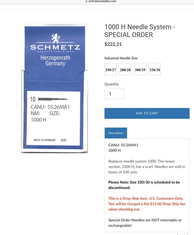
It’s $222 for a box of 100, so it’s $2.22 per needle. Far cheaper than the awls and needles I got for my Puritan.
-
Seems like we just went over much of that in this topic It’s a ballpark range kind of thing, as you said. The main things to look for are: 1. You can manually trip the clutch by holding the clutch and turning the hand wheel to make sure it works at all. 2. The clutch doesn’t let go during normal sewing, only when it really needs to.
-
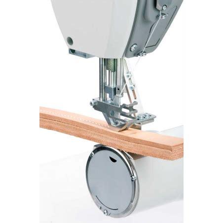
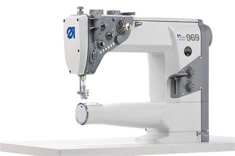
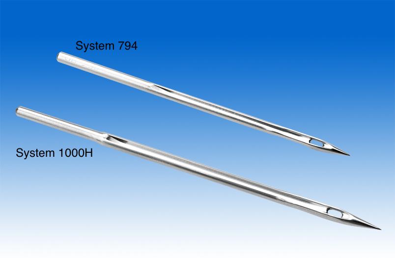
A modern machine that can sew a stack of 1.2” (30mm) is the Durkopp Adler H-Type 969 This machine is designed to use both System 794 and System 1000H needles. Using System 794 needles lowers the max thickness you can sew but you have a bigger selection of leather tips available. The System 1000H replaced the System 1000. The only difference appears to be that the new System 1000H needle has a scarf. The Schmetz 1000H needles are available by special order.
-
Here’s a video that goes over the adjustment of the bobbin case opener and what to watch out for. Your Adler machines have a nearly identical bobbin case opener design.
-
I’ve never seen one of those cable things in real life, just in that diagram I posted earlier. I don’t know the steps to replace one, sorry.
-
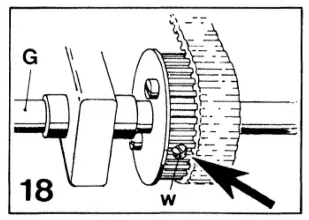
If it does have the safety clutch (which is likely) it looks like the diagram shown below. The arrow points to one of two adjustment screws, labeled “w”. The “w/18” in your post means “look for the thing labeled ‘w’ in diagram number 18 at the end of the manual” I suppose you could disable the clutch by tightening the adjustment screws all the way, but I’m not sure why you would want to do that.
-
Pfaff 545 presser foot lift and needle stop
Uwe replied to Catharina's topic in Leather Sewing Machines
Your screw that holds the rear presser foot may be going in from the wrong side (perhaps presser foot shaft is rotated 180˚) The split bottom end of the shaft has threads on one side only. The screw needs to be inserted from the side opposite those thread. That way the screw will squeeze the split shaft legs together and hold the foot very tight. -
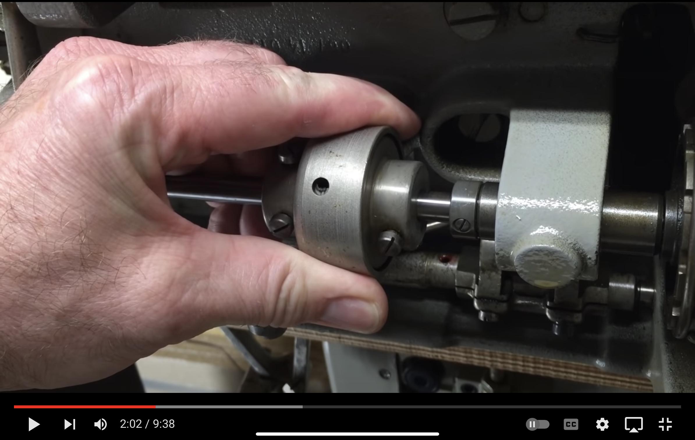
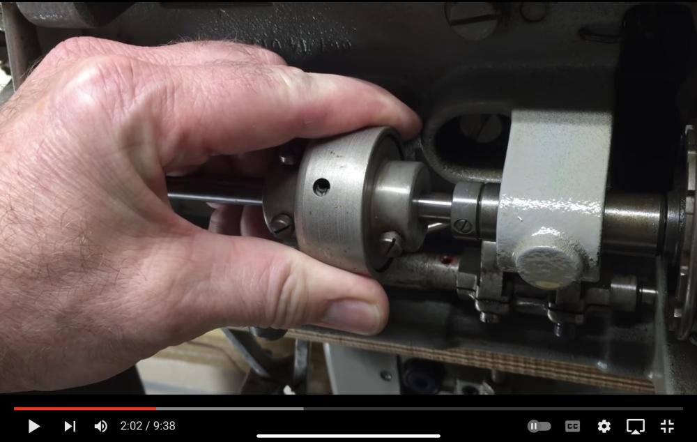
The safety clutch on the Adler 67 engages in only one position during the 360˚ rotation, so it’s not possible to engage the cluitch at the wrong 180˚ position. My Adler 67 hook timing video show the operation of the clutch starting at the 1:50 mark. At the 2:02 mark you can see the hole opposite the ball appearing in the outer hole of shell of the clutch. In this position, you can adjust the set screw inside the clutch to adjust spring pressure on the ball. This will adjust the force necessary to pop, or dis-engage, the clutch.
-
Pfaff 545 presser foot lift and needle stop
Uwe replied to Catharina's topic in Leather Sewing Machines
I edited my previous reply (several times, actually!) The walking foot timing and spring pressure is the primary suspect, I think. -
Pfaff 545 presser foot lift and needle stop
Uwe replied to Catharina's topic in Leather Sewing Machines
Thanks for that video! That looks like the needle positioning sensor might be out of adjustment or faulty. In the first video, the motor appears to advance the needle position after initially stopping in the correct needle-down position. It’s unclear to me how the different walking height adjustment could cause that. After watching the first video again in slow-motion, it looks like the rear presser foot lowers to the material after the machine stops in the correct needle-down position. Perhaps the too-strong walking foot spring mechanism is “driving” the machine to relieve spring pressure. Since the problem does not occur with the lower walking height setting, the increased spring pressure at the high setting is a suspect. Your front foot also arrives at the material well before the needle, so the walking foot timing is not quite correct. Adjusting the walking foot timing and lowering the foot pressure might help resolve the problem. -
Pfaff 545 presser foot lift and needle stop
Uwe replied to Catharina's topic in Leather Sewing Machines
This sounds more like an issue with the motor control and needle positioning system, not the machine itself. What motor/controller do you have on your machine? Does it have the heel function where you advance the needle by pressing on the pedal with the heel? A video showing the problem would be great! You have to upload the video to YouTube and then post the link here. I’m guessing to mean the walking height of the presser feet. There’s a chance that the adjustment of the walking foot mechanism and timing is not quite right and causing problems. I made a video once describing how the walking freight and timing on my Pfaff 545 was adjusted. Compare your machine to the adjustment in the video. -
On the Pfaff 145/545 line, the various sub model designations affect different, somewhat independent parts groups in the machine. Here’s my simplified description of the model variations, not claiming to be gospel or all-encompassing: The 145 vs 545 is mainly a different hook/bobbin diameter with matching hook saddle, along with take-up lever mechanism. The ABCD duty designations affect mostly hook design (thread path clearance and bobbin tension bits, but not hook size) to deal with different thread thicknesses. The H1234 lift height variations affect foot lift mechanism and walking height motion parts, along with needle bar bits and needle system (H4). The S/L material designation affects feed dog, throat plate and presser feet. The N stitch length versions affect material feed motion parts and reverse capability (N10 has no reverse). If parts get replaced over the decades with variations on the original parts, then the machine itself will eventually no longer match the model type plate codes (just like this topic is drifting away from the General Timing Question title). That’s not a problem as long as the machine can still be adjusted to make a nice, reliable stitch. It may not be worth the effort to try and bring the machine back to match the original type plate codes, depending on what has changed.

-
I’m curious how you determined that, especially the H2 bit. The H1/2/3/4 are increasing lift height designs that involves a bunch of parts that are not easily exchanged, especially on the H4. The fabric(S) vs. leather(L) designations likely just indicated if the machine initially shipped with toothed or smooth feed dog, throat plate and feet - this can be easily changed over in just a few minutes.
-
This topic has the Pfaff Model decoding info: You can adjust some machines to work with a shorter needle system by lowering the needle bar. This will decrease the maximum height the feet can lift and may cause interference between presser feet and needle bar. Sometimes that makes sense if you want similar machines in your shop to all use the same needle system, and you don’t need the high lift feature.
-
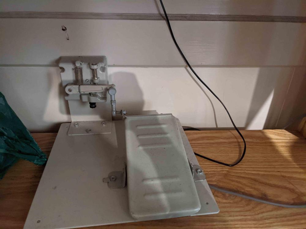
Just one more wired floor pedal reference, this time from an EFKA motor setup:
-
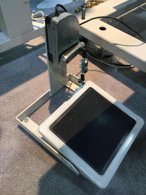
Artisan’s floor pedal for the Toro-3200BT (taken from a for sale post here on LW.). Similar concept to what I did for my Adler 69 setup. The solid connection allows for heeling of pedal for position sensor or other function. My version just had push-down movement, no lift.
-
I was thinking there might more to that signal than a simple voltage reading. Perhaps some sort of pulse width encoding.
-
We do need photos of the whole machine and any identifying plates or lettering. Otherwise we won’t know what to look for. [EDIT] I clearly have too much time on my hands. Started looking at parts diagrams for Juki DDL machines. The Juki DDL-9000 parts diagram shows a thread tension release wire (marked red) on page 7, so that’s a good candidate for the function of your cable. Your machine is likely a copy or Frankenstein of some older Juki designs.