

Gymnast
-
Posts
294 -
Joined
-
Last visited
Content Type
Profiles
Forums
Events
Blogs
Gallery
Store
Everything posted by Gymnast
-
Uwe, when I look at you link to Keystone, I guess the motor got a minimum constant speed of 100 RPM. And I have not seen brushless servo motors with a lower speed than that. Have you seen lower speed than 100 RPM? For some years ago a problem with some servo motors with this issue were debated. It may be this problem you see: https://leatherworker.net/forum/topic/41916-having-problems-with-servo-motor-speed-control/
-
Skipped stitches with stretch knit fabric
Gymnast replied to Gymnast's topic in Leather Sewing Machines
I think that canvas do not have sufficient stretch as the rest of this fabric. If I use a patch of canvas here, the forces locally to the seams can be significantly higher. The patch and the seams needs to be able to stretch. I found some limitations on what you can get of domestic sewing machine needles. When I look on websides for Organ and Schmetz, the max size jersey needle is 100/16, and the max size stretch needle is 90/14. The stretch needles should have a different scarf, so some sewing machines can catch the thread better. Some vintage machines may not be able to take advantage of a stretch needle. However there seems to be some jersey needles around of size 110/18, but this is the only supplier I found (Sharp Sewing Supplies in US): https://www.amazon.com/Titanium-Sewing-Machine-Needles-Multiple/dp/B07NQNWVP2/ref=sr_1_22?dchild=1&keywords=Organ%2Bneedles%2Bball%2BHAX1%2B110&qid=1601984198&sr=8-22&th=1 Another option may be to use thinner thread. I agree, that the top tension is less than normal. SUK needles - is it stretch needles? -
Skipped stitches with stretch knit fabric
Gymnast replied to Gymnast's topic in Leather Sewing Machines
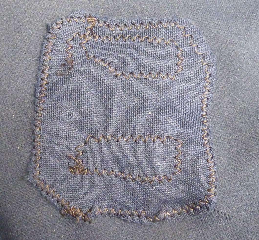
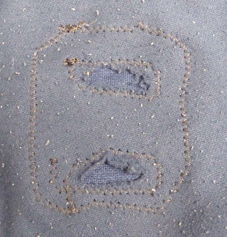
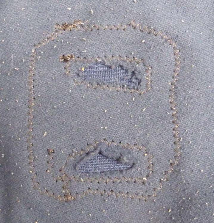
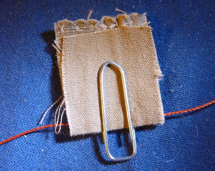
I did succeed making some patches of the cover. This is photos of the inside and outside of the cover, and the patch size is about 2½ x 3 inches. The stitch width is about 1/8 inch. Of couse I like your comment on this repair. So it is possible to sew such a difficult stretch fabric with a vintage zig zag machine. I got some comments elsewhere, that I should use thinner thread and a stretch needle for it, and it might be better. This top cover is about 7 x 10 feet in all.
-
Skipped stitches with stretch knit fabric
Gymnast replied to Gymnast's topic in Leather Sewing Machines
Thanks for the advise, @Wizcrafts I have tried to vary this check spring stroke, but it did not change anything. But what did a big change was more obvious - needle size. I have normally used size 14/90 or 16/100 with this thread. But I now tried size 18/110 and 19/120. And 18/110 worked best. Perhaps I should not have asked with a solution like that I think the theory here is, that you need to have low local thread tension at the needle eye when the needle is at its lowest position. The thread tension here will pull down the stretch fabric from previous stitch. When the needle rise the stretched fabric will pull up the thread again, so no loop or a smaller loop is created. With lower local thread tension at needle eye, the deflection of the fabric will be less, and then a bigger loop can be made. A bigger size needle got a larger grove for the thread, so the friction against on the thread from the fabric will be less when the needles advance to lowest position. When I look at the thread tension above the fabric it is zero regardless of the check spring adjustment when the needle is at lowest position. But I acknowledge, that for some other machine this might not be the case, and then this adjustment of check spring stroke would be important. I have tried sewing the same with a Bernina 910. This machine needed a size 19/120 needle to be able to sew at the same conditions. With the 18/110 needle the machine occationally made a birds nest of upper thread below the fabric. I suppose the hook stabbed the thread. This machine got a special check spring, that you cannot adjust. It also struggles more with feed tracktion on this fabric. However the stitch got more balanced in both sides of zig zag. The singer 237 produced stitches with the lock at the top fabric surface to the left and near lower fabric surface to the right. -
The problem is skipped stitches. I got a job to sew some patches on a heavy stretch knit fabric used for cover on some gymnastics mats. I currently use a domestic Singer 237 and zig zag stitching with a V69 polyester thread and a 100/16 universal point needle. Zig zag is used to allow stretch of the seam. It seems like the stretch fabric couse a smaller loop to be catched by the hook. I have tried to adjust the distance between hook and needle to a minimum, and it did help, but I do like to have a little distance here for normal use. Can you adwise some change for me, to make it easier for the machine to sew this kind of fabric? Is another machine better for this?
-
When I you see max speed in the video, is it with the pedal pressed to max speed? Is the max speed limited by a setting? It seems to me, that the lowest speed is about 1 stitch per second and max speed is about 3 stitch per second.
-
I have tried to look in more servo motor specifications, and I think it is hard to find what the lowest constant speed is. Normally you cannot find it or it is hidden very well. I guess it is because leatherworkers and other users seldom ask for this specification. Sometimes the machine got a ramp up function from start, but it do not help much. Perhaps most servo motors are designed for garment high speed machines, that do not need a bigger variation in speed. Normally the display shows the speed as Costabulary write. But I should think that 41 should mean 4100 RPM and 16 should mean 1600 RPM. But in general you do not know how these numbers translate to RPM. If the lowest speed is 1600 RPM, it is a very high low speed, and I newer heard of that before. Something could be wrong as reported in this video from 2012: https://youtu.be/X6CCxv3i4No This problem was discussed in more threads of this forum back 2012. This is one of them: I use my domestic sewing machine for many different jobs, and it have got a DIY speed control with a factor of about 68 between highest and lowest speed. Furthermore the construction of the pedal make a fast and easy control of speed: https://youtu.be/uTB8DnyYAlA I think it would be no problem for a servo motor manufacturer to make a similar speed control with very limited extra costs, if they got the demand for it.
-
In another forum, a guy using this black bonded nylon thread ended at a similar solution to have the thread roll off the spool and for more sewing machines. But according to him, he got problems with hook catching the tread, if he let the thread come off the end of the spool. I have never heard thread twisting should be able to cause such problems. Another guy reported kinks on needle thread in the shuttle area. Up to now I mainly have read about problems with kinks in the thread pass before main tensioner. What kind of problems have you seen, that should be due to thread twisting?
-
Covid-19 and disinfection of leather surfaces
Gymnast replied to Gymnast's topic in How Do I Do That?
When you search google on the subject of UV-light and Corona, at lot is going on right now. Disinfection by UV-light is not new. I know UV-light has been used for disinfection of packing materials for milk and juice in the machines just before the liquids are filled in and the cartoon is packed. It has been like that for at least 20 years. This technology is already in use many other places, but of cause now with Covid-19 at lot more places are relevant for this technology. Yes, ventilation of rooms are also a matter of consern as well as how people may come and exit the room. -
Covid-19 and disinfection of leather surfaces
Gymnast replied to Gymnast's topic in How Do I Do That?
Thank you very much for all the response. Just for the record. The problem in Denmark is quite low at the moment with 18 in hospital out of 5.8 mill citicens. Occationally we do have local areas with problems. Most surfaces we need to disinfect is covers of mats made of vinyl (PVC). Then we got some leather. I think most gymnastics clubs in Denmark will be using ordinary soap or general purpose cleaning products. This is one solution proposed by video(speaker in danish): https://www.facebook.com/PEredskaber/videos/3572701646131449/?__tn__=%2Cd%2CP-R&eid=ARC1T5L9r0qLl8aHqRsStBkEFrX2YncBTMW1itonleKpWKIpO7dGHoihAs_l_zUkGN9jktUaDZC7D586 We have some soft mats with a stretch knitted fabric (jersey) with viscose in it on the top of the mat. No solution has been found here and I think most will accept that we cannot clean them. Then we have to remove all common yoga mats. People need to have their own mat. The virus can go into the mats in ways, that we cannot clean or kill in an efficient way. Soap is effective on virus, but is is hard to use on hands without a sink. Therefore alcohol gel is used for hand disinfection only and it is used quite often with many dispensers around. We got no requirements on masks. This is not a political issue here. Scientists in Denmark do not find sufficient evidence for the use of masks, but some debate is going on among them. But it is demanded in some areas like public transport. Coaches may deside to use it, because they will touch and get close to many gymnasts. We also need to record who is there. UV-light could be a very interesting way to solve the problem. However we do know, that UV-light do affect life time of materials like PVC. We know, that we should not use these mats too much in the sun. But we need to know what the limits are, because it may not be any high dosis we need. This is a robot with UV-light moving around at its own (but of cause controlled) in a danish hospital (just for the picture): https://www.tv2fyn.dk/assens/frimaerkesamler-kan-jeg-bruge-uv-lys-til-desinficere-overflader . I saw a company selling UV-lamps saying, that everything was sold out now, so their might be delivery problems. -
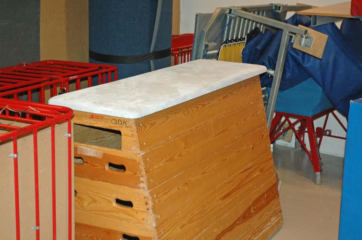
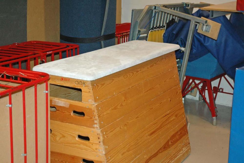
In Denmark sports associations got demands for the comming season to disinfect common surfaces between each class of training. We have got some gymnastic equipment with some leather covers. I have been informed, that substances such as alcohol should be bad for leather. What do you suggest to use? Edit: This is one equipment:
-
A normal sewing machine have a hard point in the sewing cycle, when the needle is on its way up and the eye is in the middle of the fabric. Then the friction to the thread is high from needle and fabric. At the same time the hook pulls down the thread, and the local thread tension to do this can be very high. With a needle too small it can cause the machine to stop or the thread to be damaged. I think this is taken into account, when you use tables from internet, that suggest needle sizes for threads. But this patcher is different, because the needle bar movement is controlled by a cam. The needle remains down with the needle eye below the fabric while the hook pulls down the thread. Therefore this machine might be able to handle a thicker thread for the same needle size that you normally will see for other machines. I link to this youtube video from a guy, that expects to use a V207 thread with a size 22 needle. https://youtu.be/Vv9eZbRR2z8
-
I made a collection of nine videos from youtube on the topic of speed control. You may find it insteresting. https://www.youtube.com/playlist?list=PLhBGyDo4tov8XSL24b3eiAsGBhlPJA2SF You may just skip a video if you do not find it interesting. I have got a Bernina 910 domestic sewing machine, that I occationaly use for some garment. But I do not like the speed control, because when I press slowly down the pedal, I do not know when it will start sew, and suddently it starts. Some of my other machines makes some hum noise before it starts, and it is actually nice, because then you are prepared for when the sewing starts.
-
Walking ft. comp. feed - when & why?
Gymnast replied to SouthernCross's topic in Leather Sewing Machines
A Singer 201 is compareable to a Singer 15 in performance. This is a video of a modified Singer 201 sewing leather: https://youtu.be/HIDuHjMRFWg As the video points out and show, the feed dogs leave marks on the surface of the leather. A combined feed machine will leave no or mush less visible marks on the leather surfaces. Furthermore this shown 201 have quite a few modifications, and may not take this kind of work for much time before being worn out. But it is possible for some limited projects and with limited finish quality. The modifications here include speed reducer, tension spring, presser foot with thread notch and advanced timing of feed. I do not think, that an unmodified Singer 15-91 will get you sufficient punching power and low speed performance, because the motor is quite weak and gearing is for high speed. For upholstery you can find workers that like the drop feed machines. But most upholstery workers use walking foot machines too. This is an example of this: -
Well when nobody else responded I just like to guess a little based on your information. I think in some way the stitch lever position was changed by the impact your machine had on to the road. The correct range was 0 mm to 6 mm width, before. Now it have in some way changed to -2 to 4 mm. I guess the dial with lever outside got some lock screw on to the shaft into the machine. Inside the machine I guess there might be some other kind of lever attached to this shaft with one or two lock screws. So I guess that one of these levers have got turned a bit on this shaft by the impact. You have got another lever or dial to fix the needle position from left to right. How much are you able to move the needle using this lever?
-
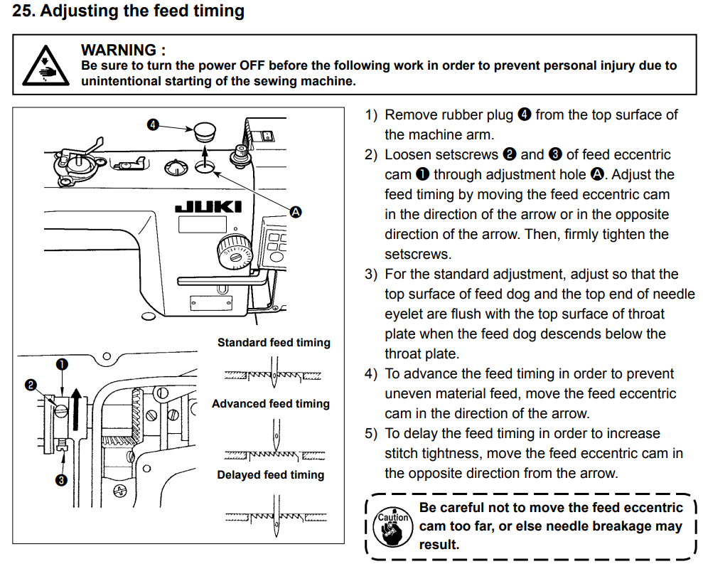
Some sewers do light leatherwork on domestic machines or industrial machines for garment with dropfeed. I found this information about feed timing from JUKI on more of their industrial machines for garment: So they recommend an advance in feed timing in order to reduce variations in stitch length. A reason might be that the thread tension is applied and stitch is formed after the stroke of the feed dog finished. Therefore thread tension do not work against the feed.What is new to me is, that JUKI propose a delay in feed timing to increase stitch tightness. In this link it is reported, that you can reduce seam pucker by retarding feed timing:Link to book, Joining textilesI think it can be so, that with delayed feed timing, the feed is part of forming the stitch and makes some of the local thread tension to do so. Therefore less thread tension is needed from the tensioners. The result is that you can reduce seam pucker. But with heavier fabrics or more firm fabrics seam pucker will never be a problem and therefore it can be better to advance timing to improve feed dog traction with such fabrics.

-
I just noticed this video from 2016 with a presser food designed with this thread notch. So I am lucky to not be the first one with this idea. This food seems to be on a high shank straight stitch drop foot machine: I just noticed, that this is a needle feed machines, so therefor the presser foot design is different. But the presser foot do have a remarkable long thread slid to the back near the hinge of the foot.
-
What is the Consew 206 of straight stitch machines?
Gymnast replied to ensitmike's topic in Leather Sewing Machines
I agree, that this is the main problem for a bottom feed machine compared to a walking foot machine. But I think, that it is not only the presser foot, that make the drag on top. Another reason for the drag on the top is the needle thread tension combined with the presser foot. A modified presser foot can reduce this part of the problem significantly as explained in the video: https://youtu.be/rBIulDuhDDs -
Yes, I agree with you, but it may be because I am an engineer too. Perhaps it just work for some of us. I did start this other thread about the subject in July: And made this little video about it: https://youtu.be/PAUJ1cVJEmA
-
I noticed that the patcher sewing machines got a special movement of the needle bar compared to most other sewing machines. This is a video of the Chinese patcher sewing in some transparent fabric. Make note of the screw that fasten the needle in top of the picture: https://youtu.be/LOliY3NHg_A The needle height is controlled by a cam in the flywheel of the machine, and the hook position is controlled by another cam in the flywheel. The needle penetrates the fabric and goes to minimum height and a bit up again to form the loop of the upper thread for the hook to catch. Then the needle is hold down at same position a long time, while the hook moves forward and pulls down the thread. Then after this hook movement have finished the needle is lifted up. For normal sewing machines, the needle position is controlled by an eccentric on the main shaft and a connecting rod to the needle bar. Then the needle eye is lifted through the fabric and further up, while the hook pulls down the upper thread. This way causes a peak in thread tension near the hook, because the friction on the needle thread is high when the needle eye passes the fabric. This video explains this problem from 0:50 to 2:20 in the video: https://youtu.be/80WASgbKIX4 It is not only the Chinese Patcher, that moves the needle this way. The Singer 29, Adler 30-1 and some older sewing machines like the Singer 28 got a similar movement of the needle. I am sure, that in this way it is easier for the hook to pull down the thread, because the friction to the thread in the grove of the needle is limited. And therefore I guess that it may be possible to sew with smaller needles than normal with these patchers. Goto 10:50 in this video to see a similar movement for a Singer 29-4: https://youtu.be/aQLre-l5RkU Perhaps more leather sewing machines are made with this special needle bar movement, but I have not noticed that. Have you? I guess that you got some other disadvantages with this kind of cam controlled needle movement, and therefore most other machines are not made this way. I think one problem can be vibration at higher sewing speeds.
-
Thread net on spool. Some people have reported a succes in using Thread Nets on the spool. Other names used are Thread sock. You can buy them from more suppliers (use Google) or you may find them used for food like when you buy garlic or grape fruits. Some use ladies nylons. They prevent the thread to drop under the spool, and add some tension to the thread, so I guess it reduce the chance of kinks to be formed right after the unwinding of the spool. Some have recommended to fold the net double to prevent the thread to get caught on the net edge. This is one video about this thread net: https://youtu.be/udl-UnLdG-4 You can buy this net as a 10 yards long (more expensive) or as 50 small pieces 16 cm long in length. This solution has been suggested some times before in this forum to help solving problems with kinks and thread drop Down under spool. I found these previous threads: I guess, than if the net press too hard on the spool, the thread tension may vary due to the thread comming of the spool near the bottom or near the top.
-
Regarding an engine, I think you will normaly think of the cams on the cam shaft, that activate the valves. The followers to the engine valves are spring loaded. The geometry of this cam described here are much different and are not spring loaded. In the years 1960-1980 a lot of domestic machines were made with spring loaded cams to control zig zag and feed dogs. Some of these cam wheels turned 12 times slower than the main shaft. If you turn this triangular geometry around the middle, you will not get the stops of movement of the follower in each end of the stroke. You can try it by cutting out a piece of carton or paper and nail it in the middle.
-
If you are a bit interested in geometry, I think you will like this short theoretical video about a widely used cam in sewing machines: I have tried to find some background information about it, but it was not that easy. Therefore I made this video. In general you will see this triangular type of cam with a fork follower (Constant-breath follower). At some other places you will see a normal excentric with a circular shape used with a bearing. But this triangular cam is very often used to control the horizontal stroke of the feed dogs. The cam may also be used to control the vertical stroke and the zig zag on a few sewing machines. It is special by keeping the fork still (no movemen) two times of 60 degrees of the rotation and the fork is moved two times of about 120 degrees.
-
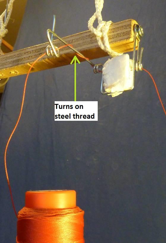
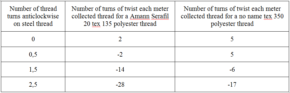
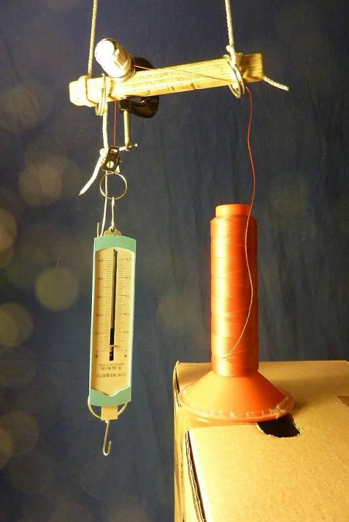
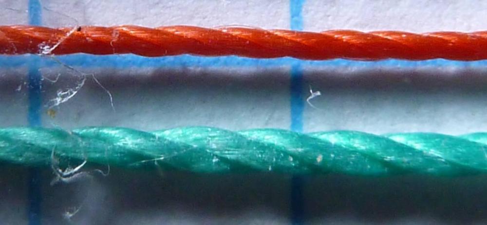
The Smart Anti Kink Device For people having issues with kinks being formed near the spool, I suggest this “Smart Anti Kink Device” to be placed over the spool and perhaps mounted on the thread stand. It consists of a bended piece of steel thread (this is Ø1.5 mm), and a small block of expanded polyurethane foam, as has been suggested by @mikesc and @RockyAussie. On the horizontal steel part, you can twist the thread around to adjust the direction and the amount of thread twisting being delivered back to the spool. You are in this way able to absorb most of the twist caused by the thread coming off the spool end, and then kinks are not formed. This is not the first prototype. The way the steel thread turns to guide the thread are done carefully to avoid a birds nest or any other change of function. But of cause you can adapt. When I do the clips test shown in first video, I get this twisting depending on how the thread turns around the steel: When you have a new spool of serafil 20, you can get about 4 turns of twist each meter with the thread coming off the spool, and then you would select 0,5 turn on the steel thread. Later on when the thread is almost empty, you get about 10 turns of twist each meter and then you set 1,5 turns on the steel thread. The foam block will absorb most of the twist from the sewing machine, but not all. So you may have to compensate a little for that too in the number of turns on the steel. I have only tried this with two kinds of thread, but I suppose you will get a similar function with other kinds of sewing machine threads. This was the main findings to be used. In the following I go into more lengthy details about it. I have measured (with a lot of testing) when kinks can be expected to form on the thread leaving a spool with Serafil 20 thread. I did that with a test set up shown here: I got a disc tension devise to adjust the amount of twist that returns to spool. Then I pull of thread and observe if kinks are formed. Twist from both spool and tensioner will increase the level of Z-twisting of the thread. With a distance of 10 cm from top of the spool to thread guide, kinks can be formed when the total twisting exceeds 8 turns each meter. With a distance of 48 cm from top of spool to thread guide, the total twisting need to exceed 15 turns each meter for kinks to be formed. Below these levels the thread may show twisting behavior, but kinks are not formed. So I can with these measurements confirm, what @Constabulary and @Bert51 already have written, that a higher thread stand better resist kinks being formed. These threshold levels for kinks of 8 and 15 turns each meter will of cause be different for different threads and different heights of thread stands. The kink threshold level can be below the level of twist the spool makes by itself by the thread coming off the end. Therefore the foam block alone making zero twist may not be sufficient in all cases and you need to actively create twist in right direction by the use of the steel thread of this anti kink devise. When I used the disc tensioner in this set up, I discovered that a very low tension of 0.2 N setting was able to create twisting up to 2 turns each meter in opposite direction. When tension was increased to 0.5 N the twisting in expected direction occurred. A tension of 1.8 N caused 24 turns each meter. The reason for this low tension behavior can be explained by the thread construction. This is a close up picture of the thread: When the tension discs press hard on the thread, then they engage the strands of the whole thread, and therefore twist are generated according to the twist of the bigger strands. When you got a very low pressure on the thread surface, then only the fibers in the strands are engaged. The surface fibers direction are parallel to the thread direction, or perhaps a bit opposite to the direction of the strands. I think the polystyrene foam block acts in the same way as the gentle discs at low pressure, and therefore they cause no twisting and to some extent prevent twisting passing through. In the first video, I used an improvised pre-tensioner, and a close up Photo is this: When used to provide 0.3 N tension, it do create a twist of 25 turns each meter. With 0.7 N tension it makes 50 turns each meter. The Anti Kink Devices can handle this too, but this kind of tensioner is not the best choice.

-
I agree with this statement, if you have got no thread twisting problems. But some people have reported thread twisting problems, causing kinks being formed somewhere in the thread path or other inregularities that cause variations in needle thread tension. So that is why I adress this question on how the disc tensioner and roller tensioner share how much needle tension they provide. You can deal with thread twisting problems in many ways too as have been pointed out already. So how the two tensioners for needle thread tension is sharing the load is in my oppinion just one way more to deal with the twisting problem. Ryan Neel have made two very similar videos on how to adjust thread tension on the Cowboy CB4500 and CB3200 machines. And I think quite many machines are like that. Here is a link to one of them: https://youtu.be/FdViQ_tv9Rc Ryan adwise, that when you need some more needle thread tension you may increase the primary roller tensioner by one turn (right) and half a turn on the disc pre-tensioner. So you always turn half as much on the pre-tensioner as on the primary tensioner. It is not exsactly the same as written in the manuals. But Ryans adwise makes better sense to me, because when you increase the tension of the main roller tensioner, then you like to have some more tension on the pre tensioner as well so you assure the grip on roller. But I have not yet found adwise from the suppliers or manufacturers of these machines on how the two tensioners should share the added tension they provide together. The only adwise is in the naming "main tensioner or primary tensioner" and "secondary tensioner or pre-tensioner". From this you may get a hint, that the primary tensioner should provide most of the tension. I have tried to measure a bit on the grip or the friction on a roller like this with 1½ turn of some different polyester sewing threads. Based on that I should recommend as a rule of thumb, that the primary roller tensioner provide 2/3 of the total thread tension, at the point where the thread leaves primary tensioner. And then the pre-tensioner should be adjusted, so 1/3 of the tension is on the thread before the roller tensioner. You like to have less tension on the disc tensioner to avoid too much twisting. On the other hand you want to avoid that the thread starts to slip on the roller, and therefore it can be risky to go much above 2/3 of tension from the roller tensioner. But with some more sticky thread, you can go above 2/3 of tension. I have to stress, that this adwise is very much as a rule of thumb, and of cause other factors influence this. And I make this adwise because nobody else have done it. Perhaps somebody else will do that.