

friquant
-
Posts
518 -
Joined
-
Last visited
Content Type
Profiles
Forums
Events
Blogs
Gallery
Store
Everything posted by friquant
-
Do you have anything stronger? Are you saying it's a hex type, like allen wrench? Is there a lock screw holding it in place, by any chance? Can you send a photo?
-
-

Sewing machine advice for a hobby/new leather worker
friquant replied to Tommy217xxx's topic in Leather Sewing Machines
I would love to have a cowboy cb3200, but it's too big to work gracefully on thinner projects like wallets. From the specs page it says the needle system is 7x3 or 794. These are very long needles, and you cannot buy thin needles in this system that have a leather point. Furthermore, when you run a thin needle with that length, they are prone to bending. Note @Wizcrafts does suggest the cb3200 in his blog on dumbing down a 441. But in general, for stitching thin to medium materials (1/8" to 1/2" total) I recommend getting a machine that takes the most common needle size, 135x16. Only in part because the needles are easy to come by in different sizes and tip shapes, but largely because the 135x16 is short enough that it does not bend easily like the system 190 or especially the system 7x3 / 7x4 / 794. Here is a photo to show the two needle systems. On top is a system 7x3, size 180Nm. On bottom is a system 135x17, size 135Nm. By the way: 135x16 is the leather-point version of the 135x17 7x4 aka 794 is the leather-point version of the 7x3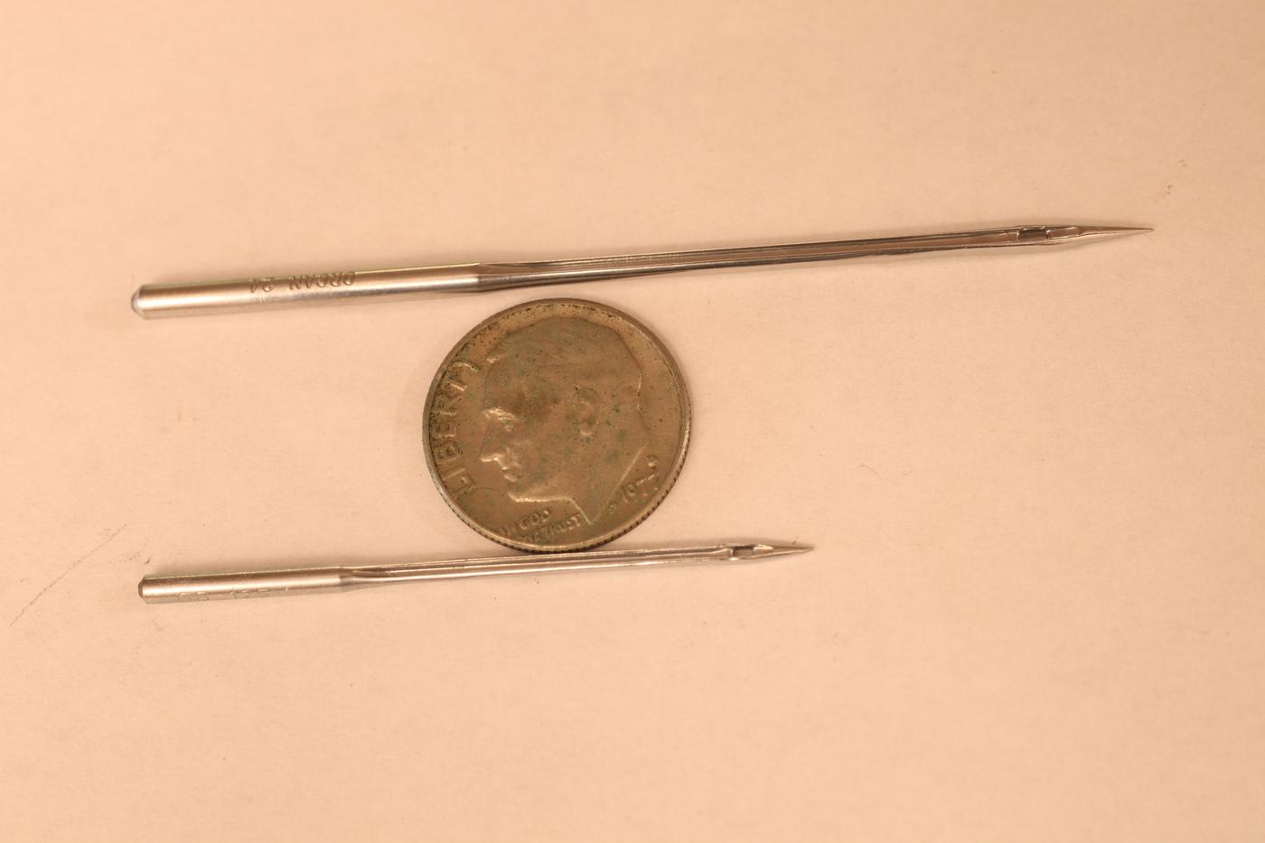
-
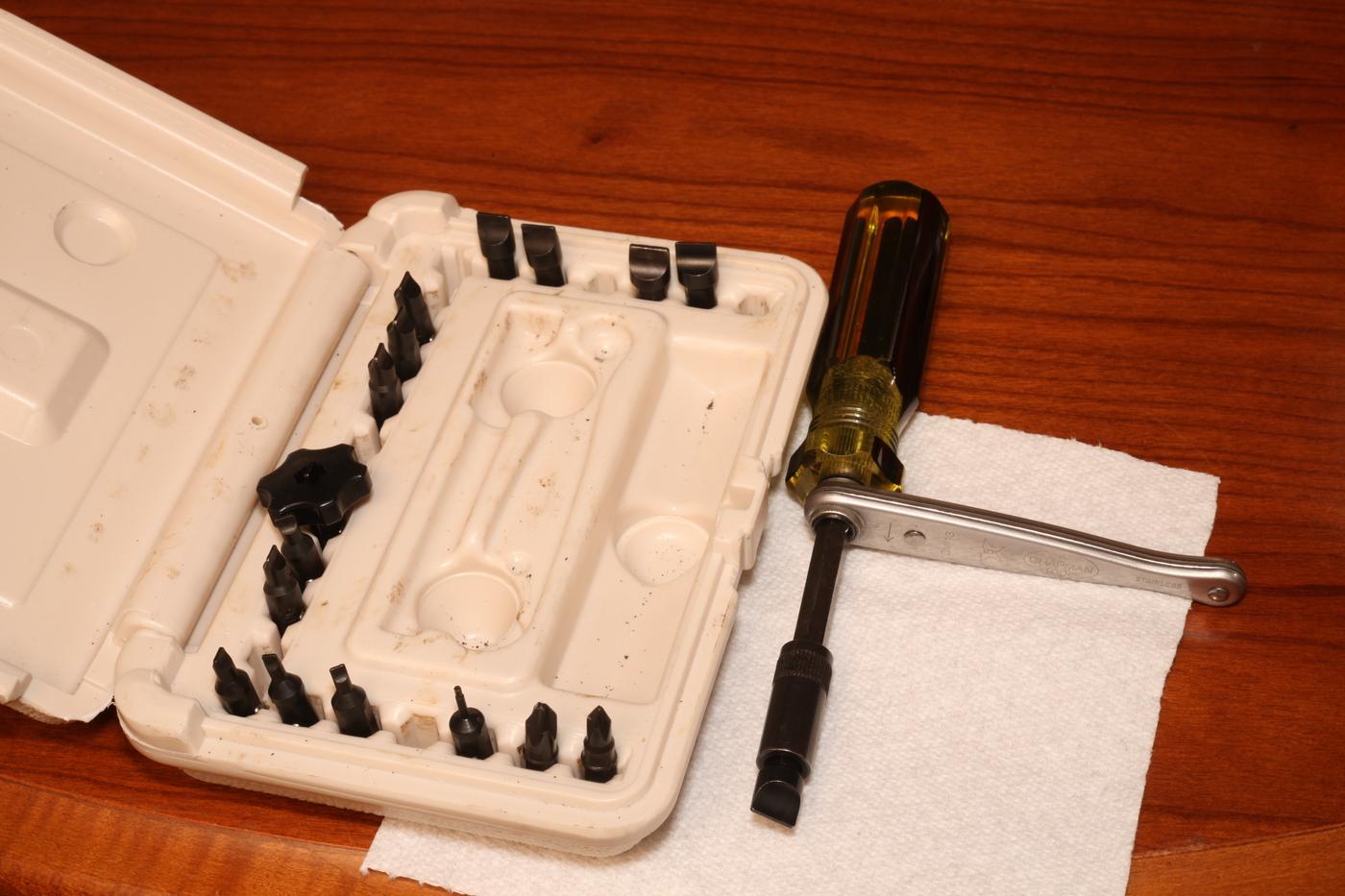
A couple drops of diesel fuel, left to sit a couple hours. That's what I use. And make sure you have a screwdriver that is a good fit for the screw. I've been using this "sewing machine" set made by Chapman. It comes with several different sized hollow-ground (paralled-sided) bits and a mini ratchet to give extra torque. Here's the amazon link where I purchased for $55.
-
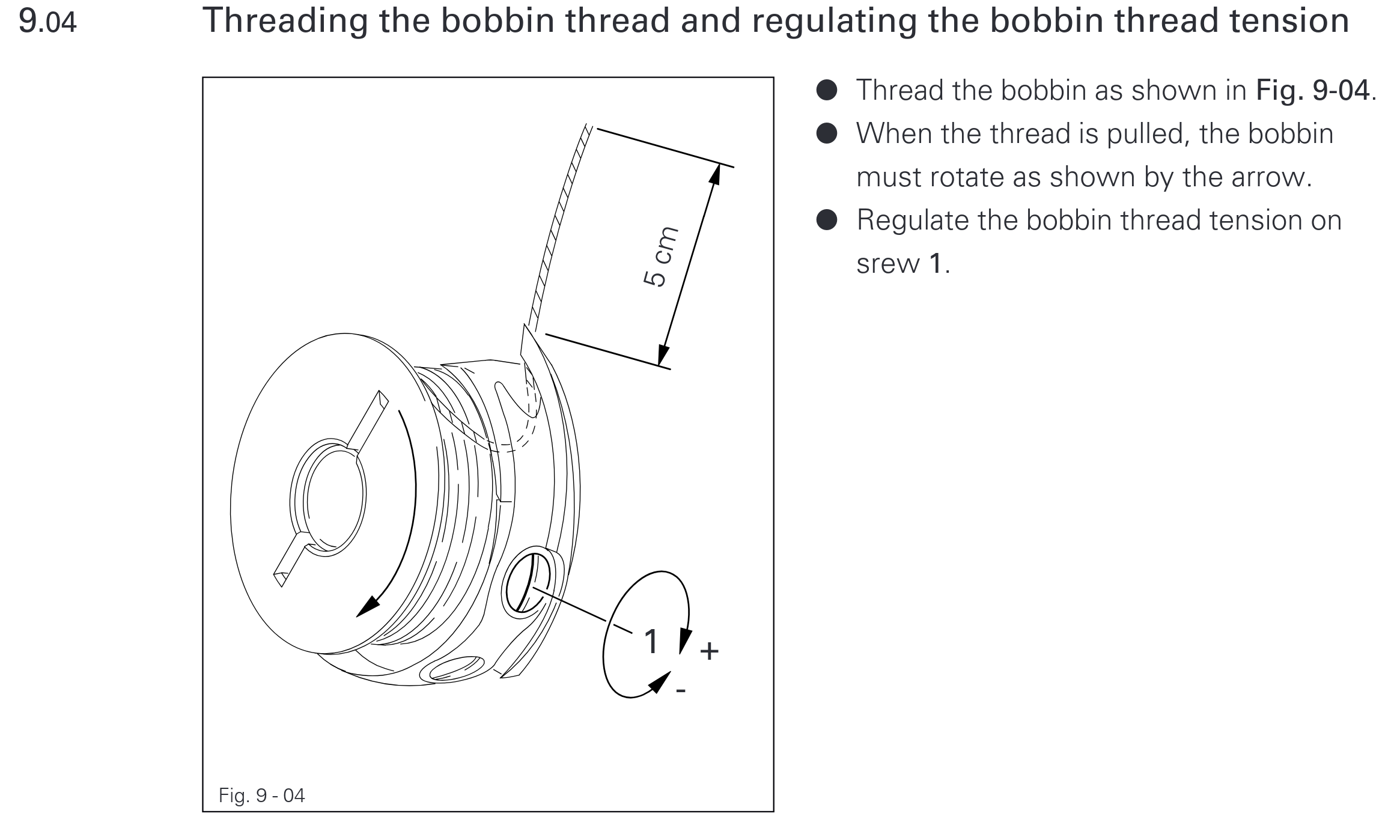
Which direction is your bobbin inserted? Here is a screenshot of the pfaff 335 manual showing the correct orientation. If inserted the opposite direction, the thread can slide out of the bobbin tensioner, which is bad.
-
Does it jump to the middle when going in reverse? After it jumps to the middle, does it ever revert to its former position? When the lower thread is in the middle, does it interfere with the top thread clearing the bobbin case latch?
-
Are you having trouble getting the machine to stitch properly, or are you asking about the fundamentals of how a sewing machine forms stitches? If the former, I suggest making a close-up video with the bobbin cover removed, while you turn the hand wheel VERY slowly and smoothly. Here is a great example of such a video:
-
Sewing machine advice for a hobby/new leather worker
friquant replied to Tommy217xxx's topic in Leather Sewing Machines
I would look at cylinder arm machines. The cylinder arm gives the versatility to sew 3-dimensional shapes, including the gussets on purses and bags. We're talking machines like the Juki 246, Juki (1)341, the Pfaff 335, or one of several clones of any of these machines. In terms of needle systems, I would target a machine that uses the most common needle system, which is 135x16. -
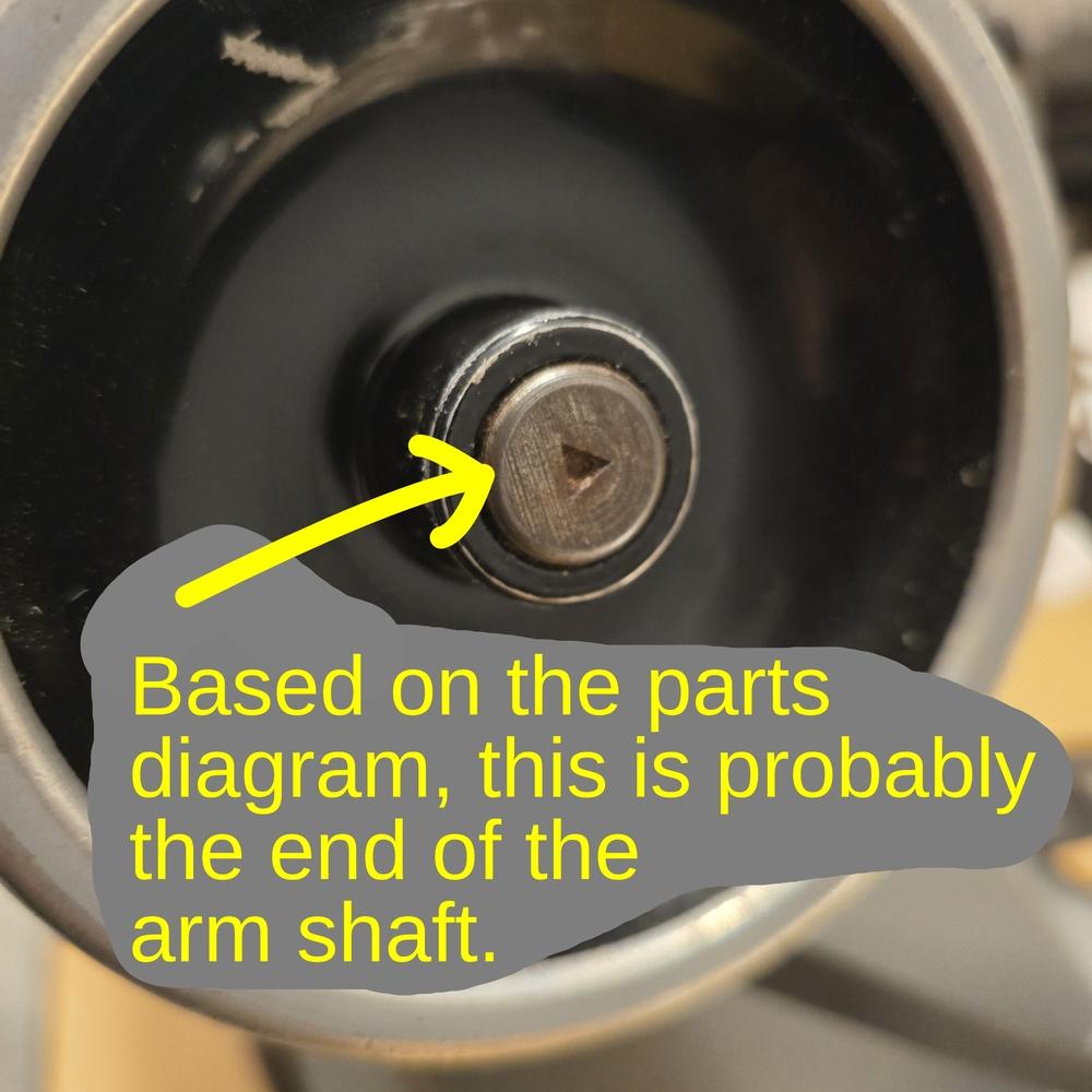
I was wrong about this. I didn't realize that the 211G does not actually have a stock handwheel screw. I assume that piece with the triangle is actually the arm shaft.
-
What are the remaining questions on this topic? Have you made progress? Are you still waiting on a part before proceeding?
-
You'll need to decide what thread size you want, and then get needles big enough for the thread and material. See AlZilla's links:
-
I haven't found many parts on a sewing machine that bend. That is, most parts on my sewing machines seem to be a very hard material that is likely to have fracture as its failure mechanism, not plastic deformation.
-
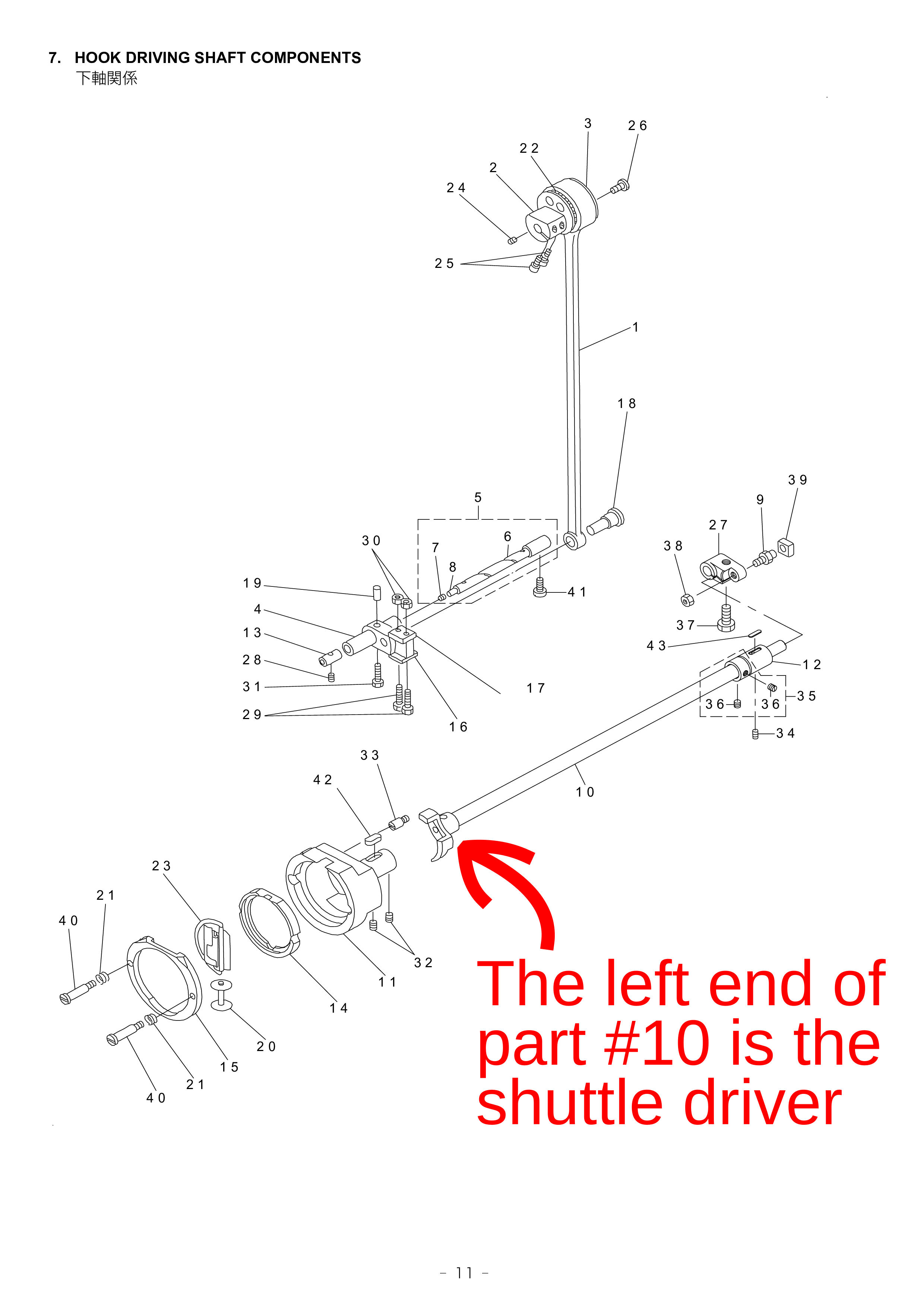
An internet search for juki 243 parts manual led to this: https://www.jukisewingmachines.co.uk/pub/media/productfileupload/j/u/juki_tnu243_parts_book.pdf On pages 11 and 12 shows the hook driving shaft (part #10), the left end of which is the shuttle driver.
-
Maybe 3D print
-
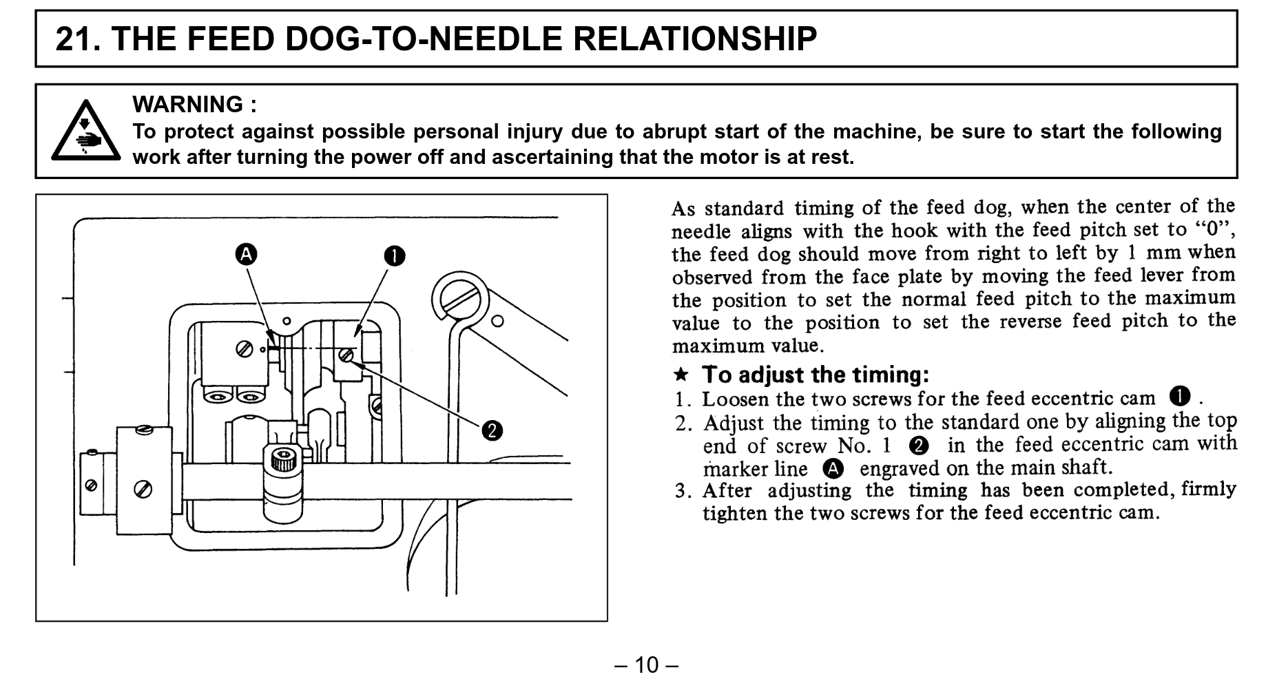
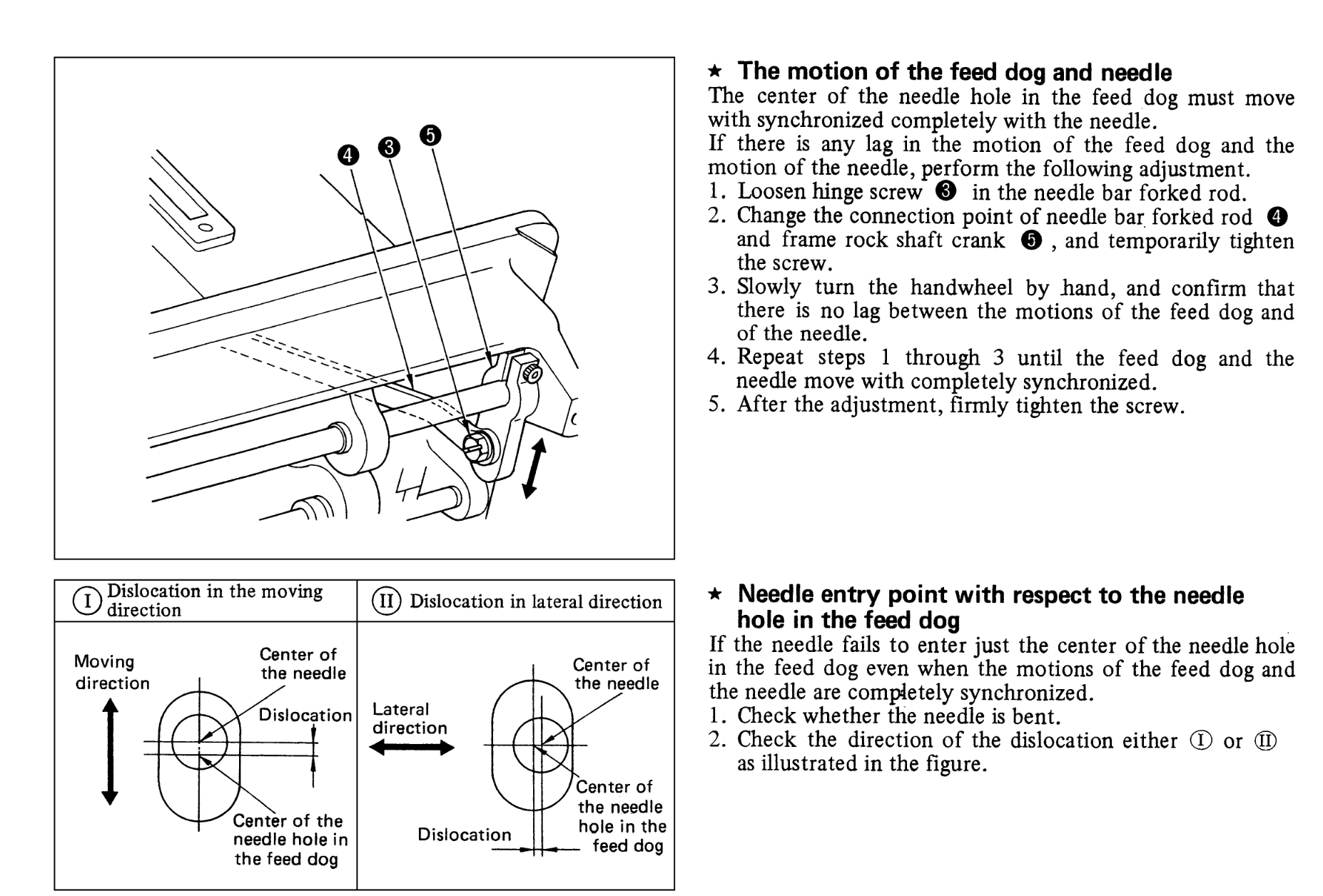
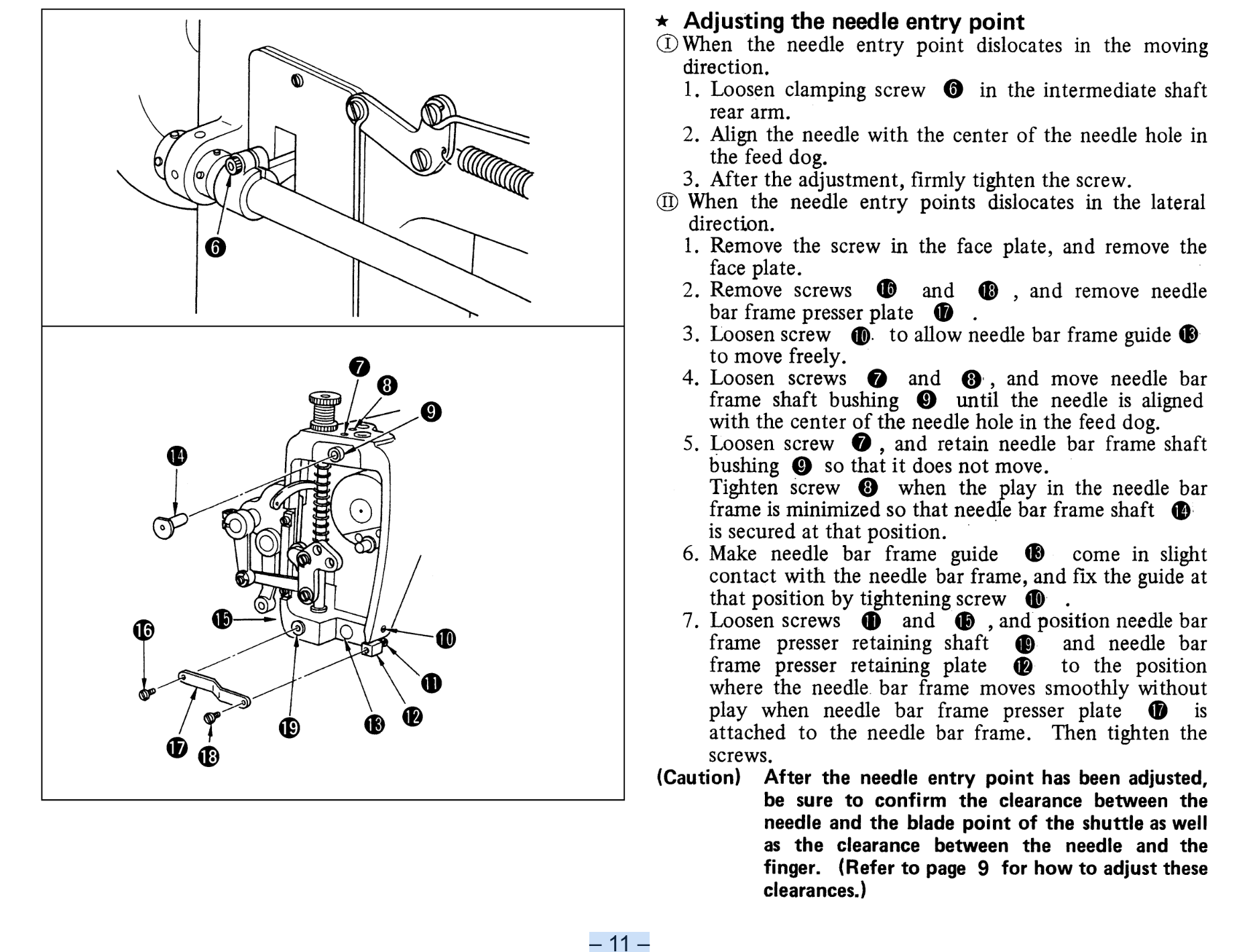
Here a link to a manual for a Juki 243: https://www.manualslib.com/manual/1638502/Juki-Tnu-243.html Section 21 (pages 10 and 11) discusses adjusting the feed dog to needle relationship.
-
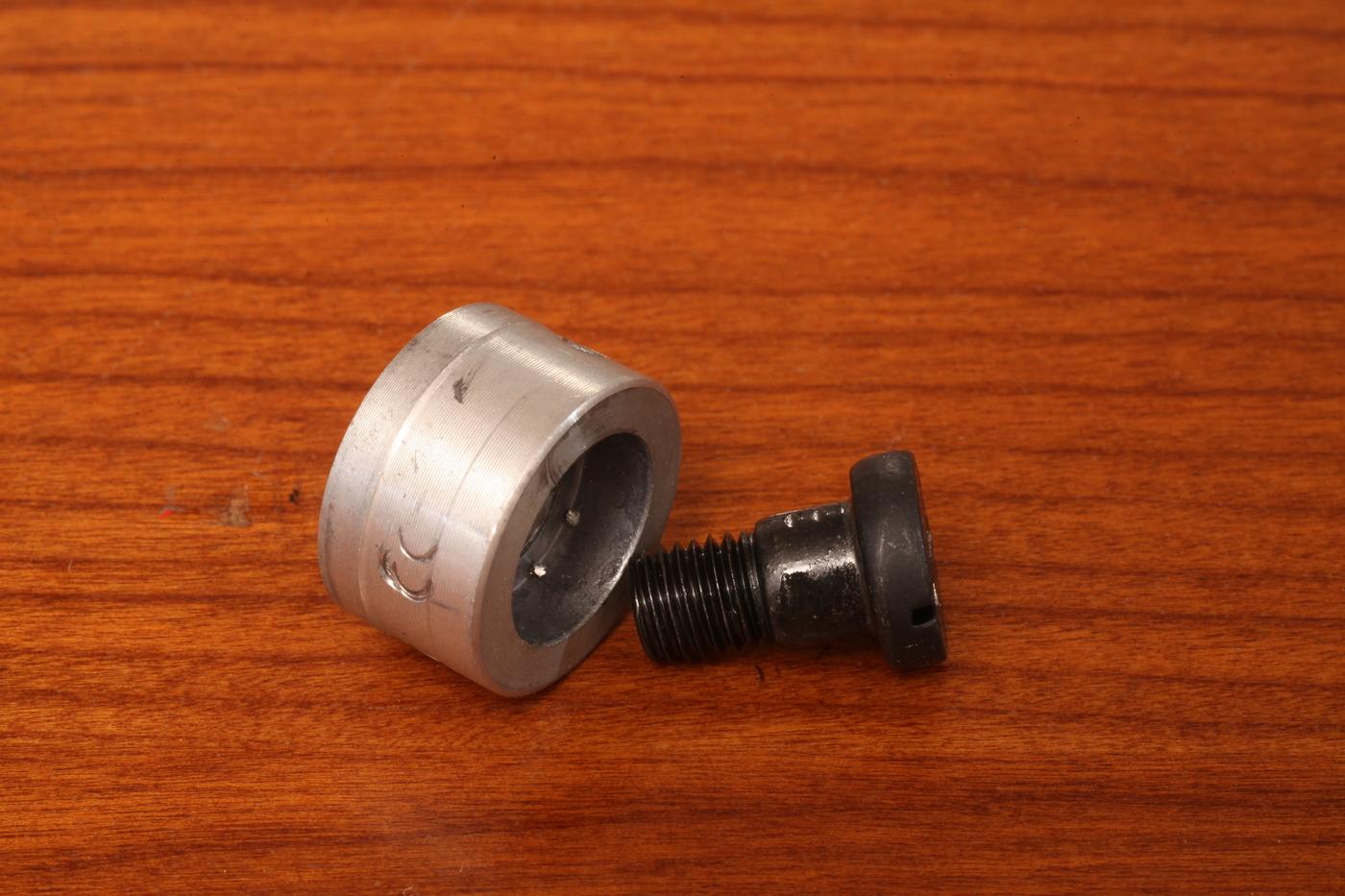
Yes, the part in your hand is the needle position sensor. Check if your hardware kit comes with a collar and extra long screw like this: If it does, remove the stock handwheel screw, and install the collar (with extra long screw) in its place. Then the needle positioner fits around the provided collar instead of around the shoulder of the actual handwheel.
-
Wowza. Even better deal 😀 Here are my notes from my "consew" digital servo controller. Based on my notes, I'm assuming the minimum speed is not adjustable, so my memory is probably wrong there. Default settings: U0: 45 | (Maximum "maximum" speed that can be obtained by using the arrow keys by end user) U2: 1 | (Reverse) U3: 12 | (No discernable difference, though the PDF calls this the "location parameter") U4: 0 | (Delay between pressing full throttle to when it instantly goes to full throttle.) (Note this is not the "slow start" I would prefer) U5: 8 | (No discernable difference) U6: 5 | (No discernable difference) U7: 0 | (Not adjustable) U8: 0 | (Not adjustable) From PDF that used to live here: https://www.consew.com/Files/112347/InstructionManuals/CSM1000.pdf CSM1000 Dual Display Controller Operating Instructions 1) The Speed Setting; UO Press R; Display UO, Press M to adjust; Display the number 5 to 70; {5 represents a minimum speed of 500 rpm, 70 represents the maximum speed of 7000 rpm}. Example 1: You need 3500 rev/min Press R: Display UO; Press M to adjust; Digital display 35; Press L to save. Example 2: You need 500 rev/min Press R: Display UO; Press M to adjust; Digital display 5; Press L to save. 2) Upper and lower needle position set; U1 Press R; Display U1; Press M to adjust; Display number 0 to 1; {0 for the next stop pin; 1 for the stop pin}; Press R to save 3) Reversing settings; U2 Press R; Display U2; Press M to adjust; Display number 0 to 1; {0 clockwise; 1 is the reversed}, Press R to save. 4) Location parameter setting; U3 Press R; Display U3; Press M to adjust; Display the number 8 to 20; (The smaller the number, the more slowly, but the positioning is more accurate; The bigger the number, the faster the location, the more not allowed), Press R to save. 5) Slow start setting U4 Press R; Display U4; Press M to adjust; Display the number 0 to 9; Press R to save 6) Other display instructions: {1}When the motor stall failure occurs, when it display E1, the motor does not work, press the R key to recovery; Many times, it is recommended to reduce the load or contact your dealer. {2}When the stream or under voltage fault occurred, when the motor display E2, the motor does not work, press R key to recovery, many times, it is recommended to reduce the load or contact your dealer. {3}When the motor has the Hall signal error, it display E4, check the motor and controller plus connection is intact, press R key to recovery many times, if not, please contact your dealer. 7) Restore factory settings: In the U mode, press the M button for 3 seconds or more. The set parameters are reset to the factory default state. ®
-
Congratulations! Can we get a good photo of the back of the machine? Specifically I'm looking for what attachment points the machine head has for a knee lift / foot lift. Having a knee or foot lift is quite convenient...worth putting in the effort to source/install one. I used to have a motor controller that said "by consew" like that. It had a minimum speed of 200rpm. If you haven't already, I suggest finding a manual for the motor controller and making sure the minimum speed is indeed set for 200. (Factory default is probably higher than that) Also, if you don't have a 45mm pulley yet, they are easy to come by, for example here: https://www.amazon.com/KKUANG-Industrial-Aluminium-Electric-Clutches/dp/B0DLGNBZFQ It will slow down your minimum speed at the hand wheel, and increase the torque at the hand wheel.
-
Maybe post a video showing how yours moves when that screw is loosened
-
Help! Singer 111w155 stripped / stuck screw
friquant replied to matthew123's topic in Leather Sewing Machines
That screw is a shoulder bolt with a very wide top. It appears to help constrain the plate that moves vertically when you lift the presser feet. That is, help prevent that plate from moving to the rear of the machine. (It has other constraints as well, which is probably how it's still functional without the shoulder bolt) -
Found a stray bushing in my Seiko CW8-B
friquant replied to WMages's topic in Leather Sewing Machines
I would check if the machine is in time. And if it has a safety clutch, make sure it is engaged. If you can, make a slow, closeup video like Karbo's here to show the timing of your machine: https://leatherworker.net/forum/topic/131845-pfaff-345-issues/#findComment-784860 and post it for us to review -
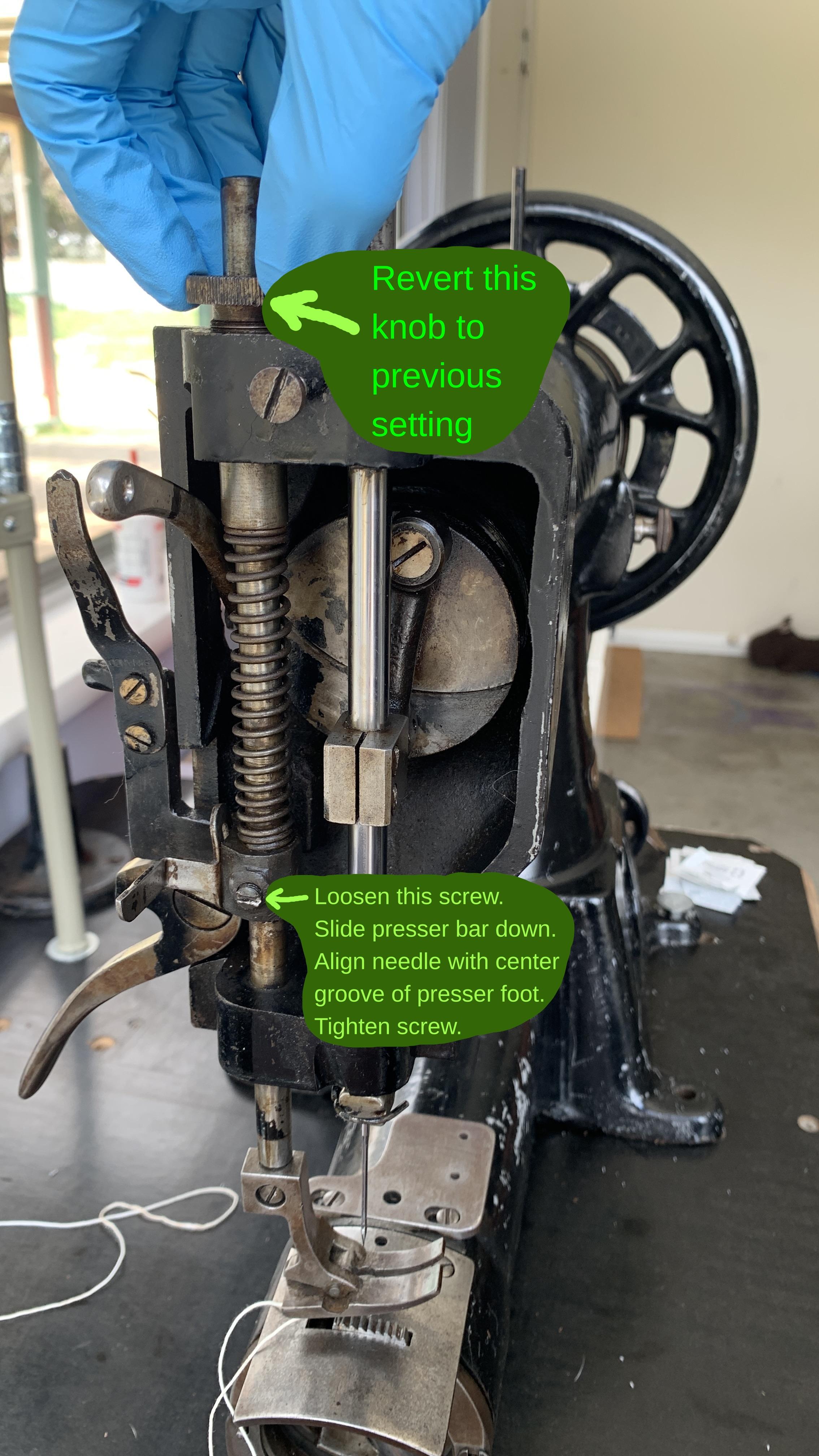
The knob that you turned increases the spring pressure. You can loosen that back up. To bring the presser foot down to a usable position, loosen the screw near the bottom of the spring.
-
Can you show a picture of what you adjusted to put the presser foot bar at its lowest setting?
-
Help! Singer 111w155 stripped / stuck screw
friquant replied to matthew123's topic in Leather Sewing Machines
It looks like you are missing a screw here.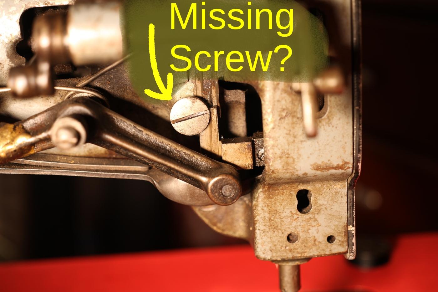
-
Help! Singer 111w155 stripped / stuck screw
friquant replied to matthew123's topic in Leather Sewing Machines
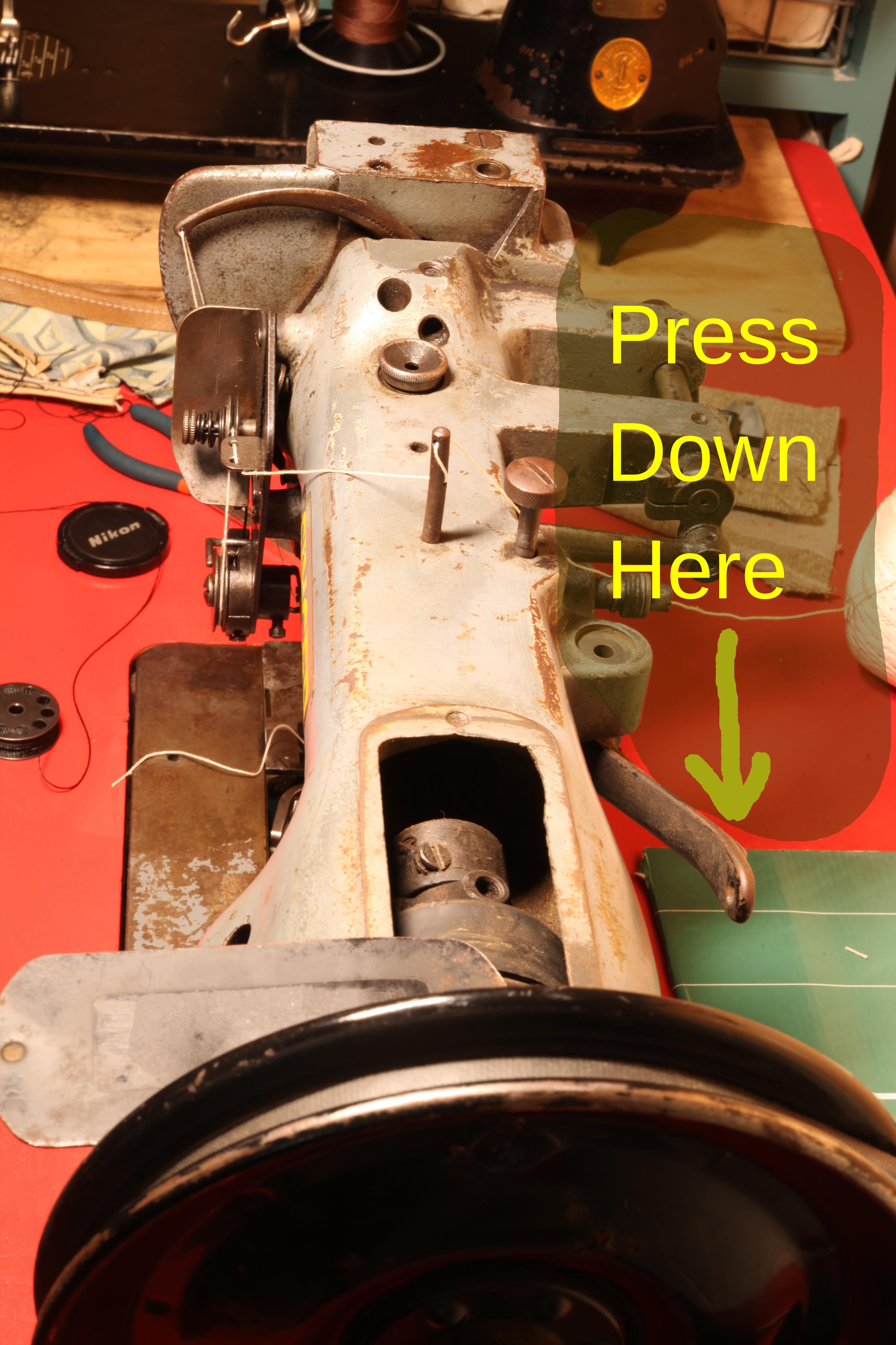
This is normal. The extra work is going into compressing the presser foot spring. The effect goes away if you lift the presser feet. Mine does not lift as far when the inner toe is down. Maybe you aren't getting enough lift. Try pressing down with your hand on the far end of the foot lift bar and see if the feet will come up.