-
Posts
794 -
Joined
-
Last visited
Content Type
Profiles
Forums
Events
Blogs
Gallery
Store
Everything posted by DonInReno
-
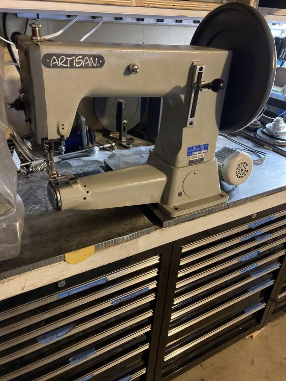
It really has been a good little table! Nice and heavy so it feels very stable even with the arm hanging out off the far end. The motor is a simple Consew 1000 with an Alpha right angle gear reducer. These are great reducers and are such high quality they are one of the nicest pieces of equipment I own. New they sell for well over $500, but on eBay the price of a nearly new one can be as low as $75. The straight version often pops up for $50. There are many less expensive brands, but the Alpha W is as good as it gets. The photo below is a similar model, but I wanted to show what to look for. The first part of the model number is the size - these things come in all different sizes, but a 060 or 075 size is about right. The other number you need is the ratio - these things come in a dozen different ratios and many seem to share the same case - the one in the picture below is a 5:1 ratio and that part of the model number is easy to pick out. The other numbers sort of matter I suppose, but these have so many options within a model that it’s more important to look closely at the output shaft, input setup and aluminum baseplate. Mine is a 3:1 and is just right with the big handwheel on the 441 clone. For smaller machines the 5:1 would be ideal - with a slightly larger pulley it would be just like a 3:1 and with a small pulley the 5:1 is about as slow as you’d want to go. I also have a 7:1 and it’s a bit too slow and the reduction doesn’t allow the handwheel to be moved very easily by hand. The output shaft comes in a wire range of sizes from huge to pretty small - if your heart was set on a small output pulley this will take more searching - often the seller has no idea what diameter it is. Going with 5:1 eliminates the need for the absolute smallest pulley. I have seen some input designs that can’t be used with a servo motor - like splined shafts or weird flex couplings. The ones that seem the easiest have a very nicely machined clamping collar that accepts a size reducing bushing - just get the correct bushing to fit your motor shaft and you’re good to go! Attaching the motor to the reducer will require drilling holes in the front plate of the motor and might require an adapter plate of some kind, but on mine no adapter plate was needed. Hopefully that gives you an idea of what to look out for. :-)
-
That pedal does look pretty good.
-

Help with old Singer cylinder arm machine
DonInReno replied to Metalhorseman's topic in Leather Sewing Machines
The order of adjustment of a hook on almost any industrial machine is to first install a new needle, then bring the needle to bottom of its stroke, then keep turning the handwheel until the needle raises the thickness of a nickel, or 3/32”. At this position the very point of the hook should be at the center of the needle and 1/16” above the needle eye. If you’re making a 1/8” zig zag then the hook would be 1/16” to one side of the hook, then the next stroke it would be 1/16” to the other side. The needle bar is adjusted up or down as needed. The hook is now timed with the needle. Then the distance (gap) between the tip of hook and needle is adjust to be as close as possible without touching. Many sewing machine adjustments aren’t intuitive, I’d suggest not adjusting anything further until you know for sure what it does - many machines have been adjusted in the wrong ways until they are are very hard to sort out. I’m guessing the person before you couldn’t figure it out and whatever they did isn’t helping. I wouldn’t mess with anything zig zag related until the hook is figured out - just set it for as close to a straight stitch as it will do and that will be close enough. I looked a bit and have yet to see an online service manual for this machine or the 107w50 that describes hook adjustment and what set screws to use. On the one picture showing the needle and hook assembly - the surface finish of the flat surface is terrible - I’d be very surprised if it was made by Singer. There is a chance that this hook is a poorly made replacement part that has never worked properly. First I’d find a manual that shows the proper adjustment, if it won’t adjust properly then look closer at a replacement part. -
That turned out good!
-

Help with old Singer cylinder arm machine
DonInReno replied to Metalhorseman's topic in Leather Sewing Machines
That’s really cool - great buy! I know I’m not helping much, but the first thing that came to mind is wondering what would happen in normal use to make a hook get closer to the needle. Did a needle break in a weird way and bend the tip of the hook? Did someone try to replace the hook and this aftermarket part is not able to fit no matter what? Did the needle shaft get bent? Hopefully it just needs an adjustment - for the last 60 years all types of people, both knowledgeable and not, have tweaked and adjusted it. If it doesn’t come up, as you take things apart or adjust them, Singer likes to use two different types of set screws, both flat tipped and pointed. Pointed set screws are designed to fit in a slot that keeps them from slipping around the shaft, but allows it to be adjusted anywhere along the groove. A pointed set screw shouldn’t be found on a round shaft or even a shaft with a flat. Not having ever seen one of these I’d first look for a set screw that might hold the hook on its shaft- it might be a couple of screws spaced around the hook. The hook’s shaft will ride in a bushing - many bushings are held in place with a set screw and that might have moved - heck that might be the adjustment. If there is no room for adjustment, but there’s a washer or shim between the hook and it’s bushing, the washer may be the adjustment, but that’s just one wild guess not knowing anything about these. Maybe the adjustment is in the needle bar frame? Im looking forward to seeing how this mechanism works. -
I bet that would work good.
-
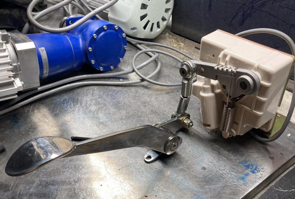
I like how your pedal turned out - nice clean look! I mocked up my little stainless pedal and it would physically work in that orientation, but the speed input box on mine is rather ugly plastic! For now I’m thinking of using it like this and maybe making a better looking smaller box. I have two of these stainless pedals and the other is for a foot lifter. I’m gathering parts to cobble together a simple foot operated air system - one cylinder at the pedal and another at the machine. :-)
-
It’s nice that they have a table top base, but it has a few things I’m not thrilled about. There is a finger of material on the base that extends under the arm so it doesn’t tip forward - this just makes the already short arm even more restricted. That top is just normal Formica covered particle board, which is fine, and it’s drilled for a normal motor mount and speed reducer. However, I bought more of this 5/8” steel than I needed and once its cut to size and edges are finished, will be a nice heavy base. The metal is thick enough that anything mounted to it just needs a tapped hole without nuts on the bottom side.
-
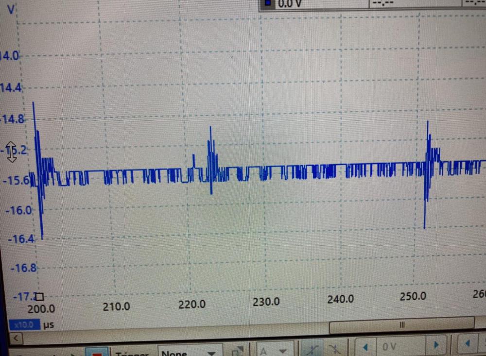
Well I’m glad I checked that speed box with a scope! What the multimeter showed as a simple 0-5v signal in the speed input box is actually something else - a 15.5v signal that gets encoded with the information in a formate I’m not familiar with. Apparently the multimeter was trying to average out all the signals for a clean voltage number. So thoughts of a ready made pedal are out and I’ll be reusing the circuit board and magnet in some form.
-
Lol Well…it’s not as bad as it sounds - or maybe it is - I have a row of toolboxes that has become my preferred workspace and it would be nice to keep the machine on the countertop there for most flat things and turn it so it points out for bags and whatnot. The base is a pretty good size piece of 5/8” steel so it’s quite stable, but it will definitely have to be separated when moving. If the dang garage was larger I wouldn’t have these problems! Lol
-
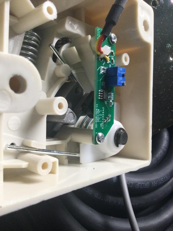
I’m in the same boat - putting together a table top base for a 441 (so it can be placed on the kitchen table or wherever), and it’s time to figure out a new remote pedal. There isn’t an easy replacement since each motor may have a different type of switch or specification as to what gets fed back to the controller. Inside the square box that the pedal chain attaches to is mostly empty space with a small circuit board and a magnet (square black thing just below the circuit board) that moves closer to a sensor on the board as more throttle is applied. This throttle box has three wires - ground, 5v constant power, and the throttle signal that gets returned to the control box. On this model zero rpm is 1.78v on the signal wire and full speed is the full 5v. There are ready made remote pedals that are made for a three wire 0-5v signal, even cordless Bluetooth pedals, but there is a risk that there is more going on than might appear . That 1.78v signal at standby might have to be established for a certain number of seconds before the control box will accept any signal for additional rpm’s - a check of sorts that the circuit is functioning properly. I’ve also heard of people having problems when changing from one type of signal switch to another because the control box is programmed to look for more than just a simple voltage - there might be additional communication that I’ll have to look for with an oscilloscope. Best case - any three wire pedal will work. Worst case - I’ll have to retrofit a pedal with the circuit board that came in my speed control box. The bad news is many of the commercially available pedals look rather industrial. I have seen some cool guitar pedals that could be stripped out and retrofitted. I’m still looking for something to catch my eye.
-
That turned out great! It’s always nice to see a home brew reducer!
-
Nice find!
-
It would be really cool to print out a dual pulley with higher ratio to replace the factory speed reducer.
-

Pfaff 1245 Random Upper Thread Loops
DonInReno replied to LordHoot's topic in Leather Sewing Machines
To me it looks like a lack of tension - those stitches are pretty loose. If adding upper tension pulls the knot to the surface, the bobbin may need slightly more tension. I’ve had a worn bobbin case that seemed to have an ok starting tension (drop test), but it had a groove worn in the tension spring and at the angle the thread was actually pulled from the bobbin case it had very little tension. I’m also wondering about the tension release - make sure you aren’t resting a knee on the knee lifter or that can inadvertently reduce tension. Thats a nice looking machine - hopefully you can get it figured out. -
If the rod is in there, but it’s not moving, then the part that pushes on the rod may be broken. We talked about it here:
-
In aluminum that size of pulley is readily available. I search eBay with “10 tooth xl timing pulley” The BF style has a hub on the side, while the AF style has straight sides. The XL size timing belts come in different widths, and with or without the metal lips on the sides to keep the belt from working off the pulley.
-
What diameter is the motor shaft?
-
Having the ability to sew thicker thread definitely expands the projects you’ll dream up!
-

Help finding a part!! Singer 111w155
DonInReno replied to chefben4's topic in Leather Sewing Machines
That’s not a bad thing - nothing wrong with having it looked at. Let us know what turns out to be the issue! Glad to help! -
I’d say no. Clutch motors are not in style for anything short of production sewing so its value is quite low - they sell for $50 used. You’ll get more for the serger if it’s complete and able to sew.
-

Yet another request for identifying
DonInReno replied to Redbeeerd's topic in Leather Sewing Machines
These are good basic machines for wallets and fabric - they usually aren’t worth much, but this one has reverse so it’s probably worth twice as much as a non-reverse model. -

Help finding a part!! Singer 111w155
DonInReno replied to chefben4's topic in Leather Sewing Machines
Just getting the parts installed is a major win! It must be something simple - there’s not much in there. -

Help finding a part!! Singer 111w155
DonInReno replied to chefben4's topic in Leather Sewing Machines
Also, here’s some good links to military manuals. The one describes total disassembly and assembly of the 111w155, but it’s pretty basic and doesn’t expand much on adjustments or explain why different adjustments are made. -

Help finding a part!! Singer 111w155
DonInReno replied to chefben4's topic in Leather Sewing Machines
Well, here’s one of my 111w155 as the presser foot lift lever is operated. Is something hitting and preventing the full range of motion, or it’s just not lifting as high as it did? IMG_0672.MOV


