

Gymnast
-
Posts
294 -
Joined
-
Last visited
Content Type
Profiles
Forums
Events
Blogs
Gallery
Store
Everything posted by Gymnast
-
Stitching issues on a 3200 with 5-6 oz veg tan
Gymnast replied to BDAZ's topic in Leather Sewing Machines
Thank you Wiz, for explaining this to me and the historic background. I suppose you mean, that you still need a pretensioner with disks in order for the roller main tensioner to operate. -
I have seen the Enduro servo motor still using a slotted optical switch to provide input signal like all the references from 2012. It was also an Enduro servo motor, that was used for the the very popular "how to" video SWFLholsters made: https://youtu.be/X6CCxv3i4No Depending of what kind og sensor is used, and how the interface is made, it might be possible to make a retrofit solution by using an air pressure sensor instead. In this way it may be possible to use a pedal like me. When you look 10:30 into this video, you see the slotted optical switch, and 3 wires are leaving it for the motor control. If this is a standard component with a type number on it, I should like to know this type number.
-
Stitching issues on a 3200 with 5-6 oz veg tan
Gymnast replied to BDAZ's topic in Leather Sewing Machines
Thank you very much for explaining this to me. The video you found from Solar Leather do also have provide high quality instructions about the check spring. -
I think a Photo would help me to help you. You can get problems like this if the pressure on your presser foot is too low, so the fabric is lifted in parts of the sewing cycle. Did you check needle size or swap needle?
-
Stitching issues on a 3200 with 5-6 oz veg tan
Gymnast replied to BDAZ's topic in Leather Sewing Machines
Yes, it is some kind of illusion to me :). I think I watched 5 other videos on youtube regarding this subject now, and they all looks equal and as on your machine. They all seems to me like the thread do not go between the discs on the main top thread tensioner. So I hope I can learn something too. With the pretensioner Ryan in the video clearly indicates, that the thread must be pulled in between the discs. But he do not show the same regarding the main tensioner. Are the tension discs different on the main tensioner? Do the thread go around the discs near the outer perimeter of these discs? I normally see the thread commes in around the post, that may be only about 1/4" diameter, and I do not see this happen here. -
Stitching issues on a 3200 with 5-6 oz veg tan
Gymnast replied to BDAZ's topic in Leather Sewing Machines
When I look at your Picture AND the video I refered to above, it seems to me that the thread is not put between the tension discs of the tensioner. I take that from the direction of the thread from the pretensioner. The thread rides on the top. It should be pulled in between these discs. -
Stitching issues on a 3200 with 5-6 oz veg tan
Gymnast replied to BDAZ's topic in Leather Sewing Machines
I did also look at the youtube video https://youtu.be/MHQBvaNkcRM I think the upper tension should be high enough to move the check spring at any time. So to me it means the upper thread tension is too low. Perhaps the lower thread tension is too low as well. Do you have any Means of measuring the thread tension? The Picture you have above, is that from before or after the stop on the check spring was changed? I would like the stop be lower than on the Picture to make Space for more movement of the check spring. -
Stitching issues on a 3200 with 5-6 oz veg tan
Gymnast replied to BDAZ's topic in Leather Sewing Machines
I am not that expierienced here. But I like you to check the operation of your check spring. For my machine - if the check spring is not operating, the top thread may not be tight when the needle hit the fabric. -
I agree with dikman, that appart from the shown modifications back in 2012, changes to an existing servo motor are hard to do. There is a lot of complicated software inside a modern servo motor, which are involved in its performance and function. However there is industrial grade motor drives for short Circuit motors (short circuit motors are used for clutch motors on sewing machines). Perhaps some of these drives can be adapted. They are sold in big numbers for general use in industry. But I think this way is not that easy either. I think the best way is to look for the better performance when you search for a servo motor for sewing machines. From this video it seems, that some of the older type servo motors (with brushings) for sewing machines do not have any internal speed sensor. It may be a DC motor with a controlable DC voltage supply: https://youtu.be/SOyQtt3eDLw
-
Hi Kgg Thanks for your attention kgg. I did quite a lot of changes to my Singer 201k. It may not have been worth it, but I like its performance now. On my channal I made a small overview of the changes, and the changes relevant for speed are given from 3 min into this video: https://youtu.be/_7ML5U_I6DU A video about the electronics is not made yet. It is like an electronic foot pedal for a domestic machines that includes feed back loop from a tacho generator and a pressure activated pedal. A very small DC motor is used as a tacho generator (speed sensor), and you can see it Pictures. Servo motors will normally have a similar feed back loop internally, but better posibilities to make fast changes in torque and have got more precise rotary encoders. However servo motors shall adapt to more kinds of machines than my setup. Furthermore the control pedal was previously discussed in this forum here:
-
I have made a demonstration video on my simple machine. It do have got a simple universal motor, a speed reducer, and I made some electronics for it that make the system act as a servo motor. The speeds demonstrated in the video are from 8 stitches/min to 540 stitches/min - a factor 68. The response to load changes and small moves are shown as well: What is your controlable speed range of your sewing machine with servo motor? Can you do better or worse? I have seen some recent demonstrations on youtube of industrial sewing machines with servo motors. And I am not that impressed of the speed control I see. For most of them, I see them jump start to a quite high low speed, and I do not like that. I did see this video from 2012 showing a resonable good low speed control, but I am not sure about the max speed and speed range: https://youtu.be/-h5U32SDZ38 Back in year 2012, several servo motor types had an issue, that they were hard to control. These issues were discussed in this forum, and I shall like to link to the four threads I just read about it: https://leatherworker.net/forum/topic/40034-question-about-servo-motors/ https://leatherworker.net/forum/topic/40168-cobra-class-4/ https://leatherworker.net/forum/topic/41483-servo-motor-mod-diy-easier-speed-control/ https://leatherworker.net/forum/topic/41916-having-problems-with-servo-motor-speed-control/ At that time a simple modification to some servo motors was introduced. More US suppliers of servo motors tried to make improvements and contacted their suppliers and manufacturers. I am however not sure, how much change to the designs that were later introduced. Electronic designers of servo motors may have limited knowledge of the needs of a sewing machine operator. Of cause an electronics designer can be incompetent aswell. The discussions here back then indicated, that many leatherworkers like to be able to sew very slow and also fast with the same set up. I think a factor 100 between lowest speed and highest controlable speed should be easy to make for servo motors. It could be from 45 RPM to 4500 RPM. However It seems to me, that most of the servo motors for sewing machines have a range with a factor about 30 only. The pedal construction can also be a limitation. However many leatherworkers were also happy with the motors they had. Others wrote, that they were not aware before the change, that they should like the better control they were able to get.
-
Thanks for your reply It seems like the old findings from 2012 is not referenced any more. The funny thing is about the case in 2012 was, that it was a new man in the busines that started sewing and was unhappy with the disign. Most others would just accept the servo motor and "that you just need to pratice" to get better - its is not the machine that has a problem. I can confirm one called Yuma 550 watt, with another design shown here: https://www.youtube.com/watch?v=w7sh972qqmk It uses a magnet and a hall element magnetic field strength sensor. So the movement of the magnet changes the field at the hall sensor. However it cannot be a perfect system either. The earth magnetic field is about 50 micro Tesla, and it may somewhat disturb with the speed depending of the position in the World and direction of the table. However I do not know its performance regarding low speed. What I see is, that the lowest possible speed of the machines seems to be quite high (in my opinion). I would not be satisfied unless you could reach below 30 stitches/min. But it seems to me, that the speed jumps up from zero speed to a quite high low level speed. I know something about Electronics and Electric motors, and a well designed servo motor should have no problem in operating with a factor 100 in speed from lowest speed to maximum speed. And you should be able to control that with a good pedal as well. So I cannot figure out why this is not done with servo motors for sewing machines. This video from 2012 show this good low speed control with a modified servo motor: https://youtu.be/-h5U32SDZ38 I noticed these two recent videos from 2018 with quite high low speed of about 120 stitches/min. It is a Ho Hsing G60 servo motor on Pfaff 1245: https://www.youtube.com/watch?v=oJVlq_L16ew This other kind have the low speed limit of about 60 stitches/min with Sewpro 1100 NPFL: https://www.youtube.com/watch?v=UT2CRg2HiYY You have many more videos out there, they all seems to have this "to me strange" low speed limit. And many of them do only have a span of about a factor 5 from their controlable lowest speed to their max speed. Perhaps I should make a new thread here asking about this.
-
I just noticed this topic, and I hope it is in order to revive this thread about slow speed control. I have noticed some recent youtube videos showing the speed control of servo motors. And I was not impressed by the slow speed control. Then I found these two 7 years old threads here dealing with the same problem and making a simple modification to some of the motors. https://leatherworker.net/forum/topic/41916-having-problems-with-servo-motor-speed-control/?tab=comments#comment-260742 https://leatherworker.net/forum/topic/41483-servo-motor-mod-diy-easier-speed-control/?tab=comments#comment-258131 Did the servo motors on market improve regarding slow speed control the past 7 years?
-
My old Durkopp is driving me up the wall!
Gymnast replied to toxo's topic in Leather Sewing Machines
Good, that the machine works much better for you now. I see now, that I did not read your text carefully about your change in thread size. I do not have use for the M60 and hopefully you find some other guy able to use it. -
My old Durkopp is driving me up the wall!
Gymnast replied to toxo's topic in Leather Sewing Machines
I noticed, that you use M60 thread, and it is like tex 40 or tex 45. In your latest video you sew three layers of veg tan leather. I think your thread in general will be too thin for that, and I should use at least tex 70 (M40) to this kind of material. I think this thinner thread will be easier to break for materials like veg tan leather, because you need to have quite high thread tension to pull the lock into the leather. I suppose you have checked the lower thread tension to be right and not too high. Your video shows the thread to be damaged before breaking right behind the check spring. I should check the tensions discs and all the thread guides around it for any wear that may damage your thread on its way. It may also be the hole in the thread take-up. If you have got a dynamometer to measure thread tension you look for any anormalities in tension, when thread passes the tensioner and its surroundings. You may also feel tension variations by hand while pulling the thread there. -
How To Run A 3 Phase 380V Motor On 220V
Gymnast replied to Constabulary's topic in Leather Sewing Machines
You are right, that you can do this wiring change to a 3 phase motor. But this change cause increase of the power losses (to heat) of the motor and in particular when the motor runs with no load. For larger motors and machines that run long hours, this increased power bill can be uacceptable. -
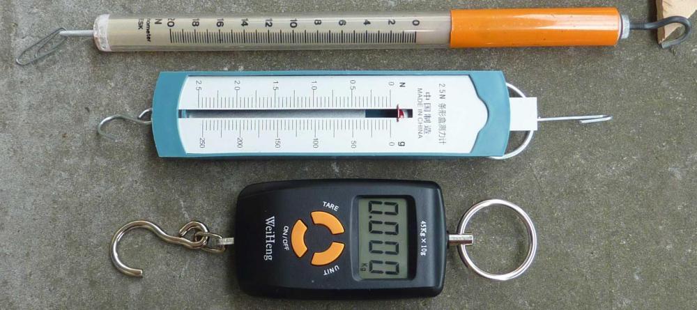
I think many expirienced leatherworkers will argue, that instruments to measure thread tension is not needed. You will be able to feel and see when the right tension. And you can quite easily find out what is wrong with the tension, when problems occur. I am not an expirenced leatherworker, and I have been using a spring dynamometer to measure thread tension. A dynamometer is an instrument to measure force. It has helped me to find problems with thread tension, and for some projects I write Down what the lower tension and upper tension should be to make a good result. When you use the same machine for different threads, it is nice to be able to get the right tension again without a lot of trials on fabric. When I search on "tension" in this forum, then I can see, that this topic is quite often debated and people ask for help. I recommend to Invest in a few spring dynamometers. This issue was discussed before in this thread a year ago, so i just like to link to that: I have now tried two kinds of instrument, and they are pictured below: The two on the top uses an internal steel spring, that is elongated by the force. The Electronic type have a very large range with a resolution of 0.005 kg and able to measure 45 kg. I think you need two or three spring dynameters for different max forces to cover your needs. But these instruments are cheep. One issue is the variation in thread tension. I think the spring dynamometers will give you a better indication of variations than the digitale scale. The digital scale do have some time delay and averaging of the real forces. I did make a small video on the use of a spring dynamometer: Spring dynamometers are often cheap to buy from some suppliers of equipment to physics education in school. One Chineese supplier with some different types is this: https://www.ebay.com/sch/m.html?_ssn=ecdepot&LH_PrefLoc=&_from=R40&_trksid=m570.l1313&_nkw=dynamometer&_sacat=0
-
This is a puzzle. I suppose, that when you find the problem it is quite simple. But now it is hard, and it has been so for some time. I just like to ask this question. What prevents the new hook assembly to go further down as it should? Are you able to put in small strips of paper or thread to feel where this hook assembly is stopped in its movement downwards?
-
When I look at your second Picture, I do not think the plate can be much thinner or at a higher position above the bobbin Lock. So agree on SARK9 remark on looking to the "bobbin basket group of components". For some reason they seems give a higher position than they should. You may not know the real storry to this machine - it may have been dropped and some components have moved or bended.
-
Well, I actually have solved my problem. I was just interested in finding out, if it should be possible to place the spool upside Down. Then I reported what I saw. It is far too early to say anything about how it will Work in all kind of situations and different threads. But it may be a way to go for some of you. I think kggs solution with horizontal holders is an excellent idea. In this way the unwinding from spool makes no twisting at all. But it may also have a few issues. Unfortunately neither SLC nor American & Efird replied to the e-mails I send to them.
-
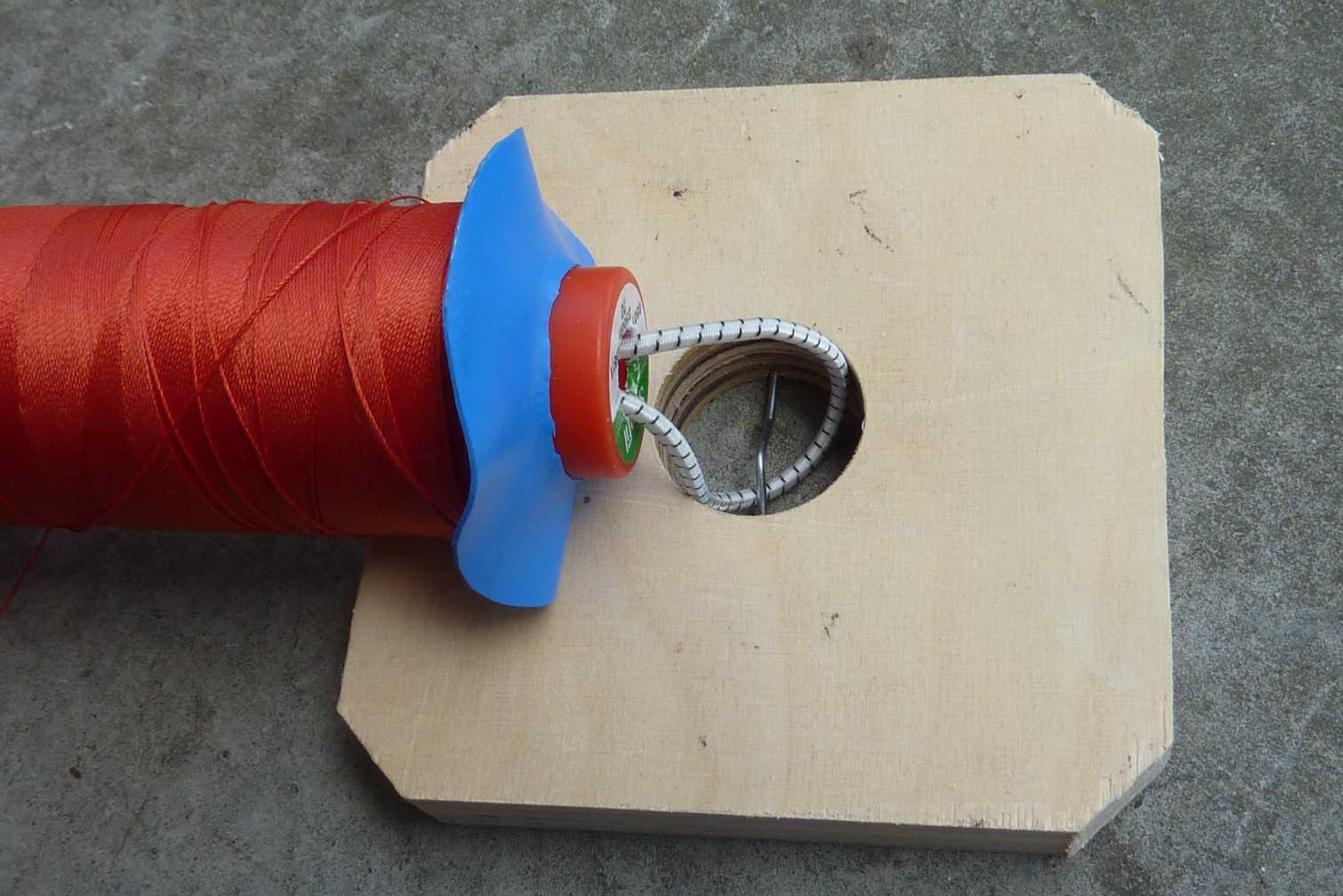
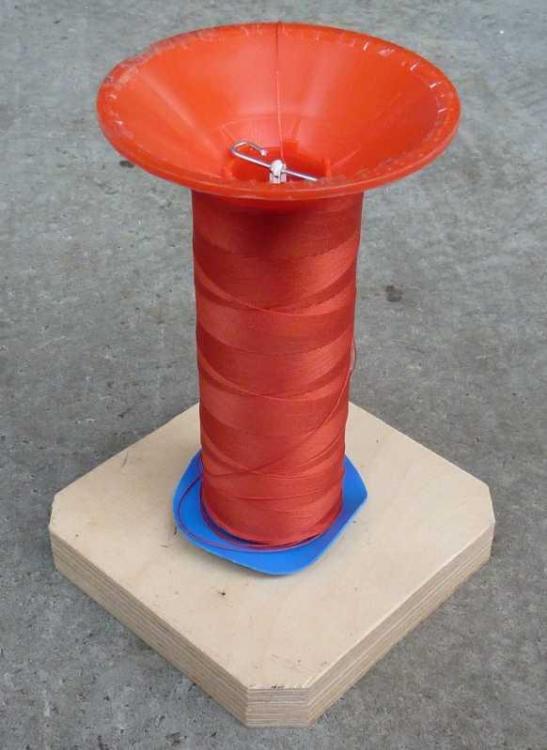
I agree with you. I tried to cope somewhat with this problem (look at picture) and I did not see it in my trials. If some of the loose coils of thread drops to much Down and around the cone of thread, you can get peaks in thread tension or perhaps catch the thread. Please notice, that I placed a tape around the edge of the base of the spool. The thread passes this edge, and it needs to be smooth. Otherwise the thread easily catch a scratch there. Perhaps someone else have a better idea to make upside Down of such a spool.

-
I tried a test with the same thread spool upside down: It did Work. In my case the first thread guide is only about double hight, and it may be somewhat low. I repeated the three ways of threading like I presented above in second video. I was not able to get kinks with any of them. One way of interpreting the result is this: As presented in first video, then any tensioner or simple thread guide will twist in one direction only. The only way to twist otherwise is to make the thread run anticlockwise around something while going forward. So in most cases you will get only one way of twisting from the machine. When the unspooling at the same time makes twisting, so the thread near the spool becomes even more twisted, then kinks is created. With the spool upside down, so the thread comes off anticlockwise, then the twisting in most cases will be less near the spool.
-
I think you are right regarding the photos with the presser foot notch and wheel foot. The tension in the thread is going to somewhat bend the needle to the back. This will not happen on the normal foot, and it can actually be a reason why a normal foot is, as it is. You may not like that to happen, and it may affect the working time of the needle. When I carefully look at the sewing cycle on this machine, the thread take up will take off tension before the needle hits the fabric. Therefore it should not affect the stitch length.
-
You are right. I think it is how the machine is. The grove is to the right, at it causes the thread to be hold in a more difficult pass around the needle shaft. It have made me thinking about a possible modification by moving the thread guide on the needle shaft closer to the needle centerline. Yes. And perhaps I should have the Work done instead of all this :). But i think it is a Little funny too. Forcing this machine to its limits do also require more trials.
-
Oh, thats a special announcement about my credibility. I did not expect that in this forum, but it is after all the internet of today. I am suppriced to learn, that someone used to sewing can think, that sewing like that can be done with an inverted needle. Sometimes the good thing about internet is, that some matters can be easily verified by people who want to do that. There is over 50 videoes on youtube that show details on how Singer 201 make stitches, the direction of the grove of the needle, and how the thread will pass the machine. Make your own judgement on who is creditble. This is one of the videos: I am sorry, if some of you will feel uncomfortable with me showing some test results. I actually just write down what I see, measure and what I think about it. Use it and think what you like and make your comments. I do know, that many here have a lot more expirience with sewing than I have.