

SARK9
-
Posts
391 -
Joined
-
Last visited
Content Type
Profiles
Forums
Events
Blogs
Gallery
Store
Everything posted by SARK9
-
Not familiar with your exact machine, but it looks (superficially) similar to the same area on a Consew 206RB4 , which had a similar problem that was significant enough for them to add a thumb-button on the RB5, which now has to be pushed in to change the stitch length. Many of these *clone* machines are nearly direct copies of older designs, so someone who has an RB4 may have a come up with a workaround, if yours IS based on the consew. -DC
-

Can anyone help me with a running a 3-phase Juki at home?
SARK9 replied to williaty's topic in Leather Sewing Machines
For what its worth, one of the larger sewing machines I have came with similar automated functions....a Mitsubishi Limi-Stop Z servo that was all 3 phase....it had the usual factory stuff...backtack, needle position, foot lift, reverse...the mechanical stuff was pneumatic but the actuator valves were controlled by the electronic brain on the main unit. What you may find interesting was it was powered by a *static phase converter* and plugged into a typical household 220V outlet. The small HP requirements for your machines may make that reasonably economical compared to an actual roto-phase setup. The bonus is, no motor running the whole time you need the 3ph power. I've used one static phase converter in the past (came with a new Powermatic model 72 table saw I bought) and I never felt like it was underpowered when ripping long 2" Honduras Mahogany boards down to width. I use a couple of 5hp roto-phase motor conversions to power the machine tools my current shop, and you may find the droning of the motors a bit annoying if they are indoors with you. -DC -
DIY Electric Bobbin Winder - Singer 111 and 45K Type Bobbins
SARK9 replied to Constabulary's topic in Leather Sewing Machines
You can modify the shaft in such a way that it will be semi-universal..(I have no 45K or 441 type bobbins to test/verify). ..The bobbins I wind on this one are: (L to R) Singer 144w/Juki LG-158 Seiko SK-6 (132K stye), U style, M style, G style, A style, and Singer 29k (large) style. -DC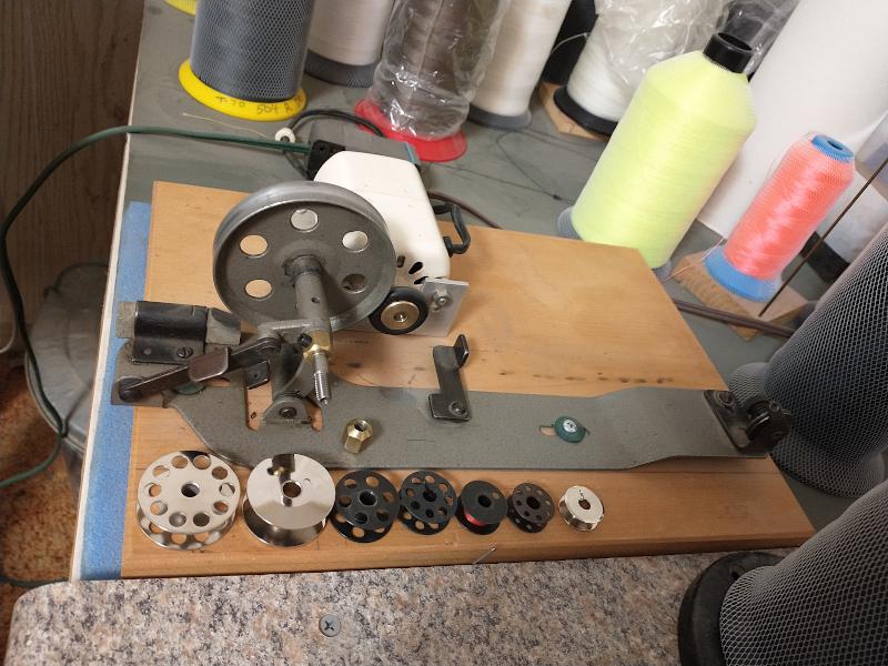
-
Most of the common walking foot mechanisms (as seen on the Singer 111W class machines) are very similar in construction and adjust in nearly the same way. Uwe has uploaded a video with a segment covering this adjustment: The manual also describes the procedure: https://s3.amazonaws.com/a.teamworksales.com/CONSEW+PDF/CONSEW+NEW/CONSEW+206RB-5+INSTRUCTION+MANUAL.pdf I would point out that many of the *bargain priced feet* available from our Asian trading partners are absolute crap and wildly variable in the as-installed length, this will produce lots of puzzlement as you swap out foot styles. The feed dog height can also be poorly adjusted as well. -DC
-
If you can get the right parts. You will need all the usual stuff: Inner and outer foot, feed dog, needle plate and possibly a needle bar as well. I can't tell if your check spring is still there for the thread controller assembly, but both sets of tension discs and springs are missing. If you use the 144W style of outer (presser) foot, you will have to rotate the presser bar 90 degrees. The Juki LG-158 I have has single and double needle versions....mine was the 158-1 (single) but I didn't care for the original setup for those same parts and made some with a more specific design for my work. The good news is it seems that some of the Singer parts are more plentiful, but there's not really a lot of variety. -DC
-
Also the Consew 744R and the Juki LG-158/158-1 have some parts in common. -DC
-
Many of the longarm machines (like my Juki 158) have the reverse mechanism operated by a chain located near the back underside of the casting....as you can imagine, its tough to reach over to operate a reverse lever that is 30 inches away. They were equipped to use a foot pedal for reverse. -DC
-
Are Zig-Zag machines exceptionally hard to find?
SARK9 replied to williaty's topic in Leather Sewing Machines
-
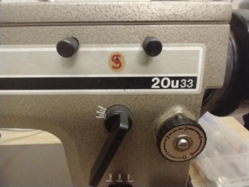
I've got 9 industrials in two former bedrooms upstairs....all but 2 are on the normal sized industrial tables, and those 2 are on custom made tables that are shorter but wider. Lightest is the Singer 20U33, heaviest is the Seiko SK-6. The Juki LG-158-1 on its stock issue Juki table will NOT be making the trip upstairs LOL. -DC
-
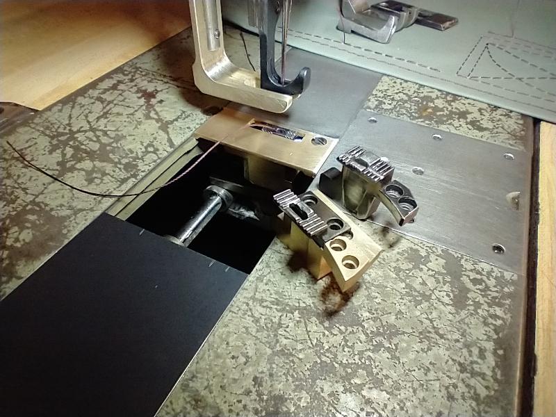
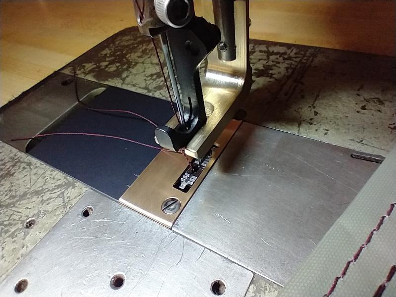
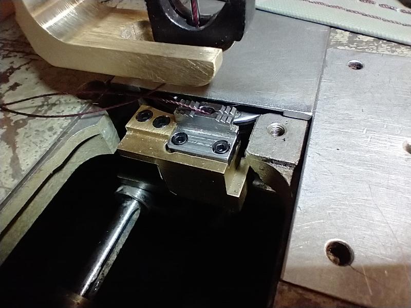
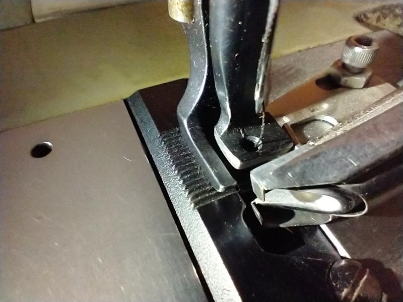
It certainly helps to have the clearance "hole" in the raised needle plate.....it allows the outfeed lip of your binder to recess below the bed level of the machine and have the tape flow more smoothly with no vertical step. ------> why is the feeder only half the normal one in length 111g models It is advantageous to have the lip of the binder mounted as close as possible to the needle...and the shortened feed dog and inner foot allow this clearance when the binder is "buried" in the raised needle plate.


-
After making my own utility cover plates for several brands and ages of machines, its fairly obvious that their tolerance for the dovetail milling operation used in that design must have been pretty....open. I'm guessing that if you made a cover plate to fit the higher end tolerance passably well, it wouldn't even drive in some of the beds with the low end of the run. They probably modified the "cheaper part" to allow some compensation for variables and wear, and the 'spring' shape left on the narrow slide of the slot is able to adjust to the *feel* desired. I have to individually fit mine to the machine it will be used on (mostly for binder mounts, edge guides etc) ...and of the five vertical axis machines I've had which share this design, only 2 of them could share plates. My problem is/was, that the plate needs to fit the dovetails pretty well because of the setscrew-type clamp I use to secure the plate after adjustment. If too loose, this locking screw lifts the whole plate nearly out of engagement with the bed, and the original singer slotted spring can't resist the lifting force's tendency to wedge it back inwards. So....hand fitting it is. -DC
-
Presser feet: Singer 144w* --> Juki LG-158-1
SARK9 replied to SARK9's topic in Leather Sewing Machines
Thank you Bob! A 158 followed me home and I'm in the process of deciding whether to give it a name and keep it or turn it over. Thanks again- -DC -
Do any of you happen to know if the Singer 144w presser feet (with the typical "111w style" blade on the lifting foot's attachment) can be used on the Juki LG-158 single needle machines (which have the slot in the presser bar with a transverse orientation) just by rotating the Juki's presser bar? Most of the 158s I have seen have the crosswise slot in the presser bar, but I HAVE seen a couple using feet with the inline Singer-type slots. Just checking. TIA- -DC
-
Consew 226 thread snapping/bobbin issue
SARK9 replied to sixpence668's topic in Leather Sewing Machines
In your video, you can see a small square tab just about touching your needle plate. There is a slot on the underside of your needle plate this tab is supposed to be confined in...this prevents the bobbin case from rotating. Remove your needle plate, rotate the bobbin case until that tab is nested in the slot, and reinstall the needle plate. If your bobbin case opener is correctly adjusted, that should correct it. -DC -
Consew 206RB-5: Not picking up bobbin thread
SARK9 replied to MtlBiker's topic in Leather Sewing Machines
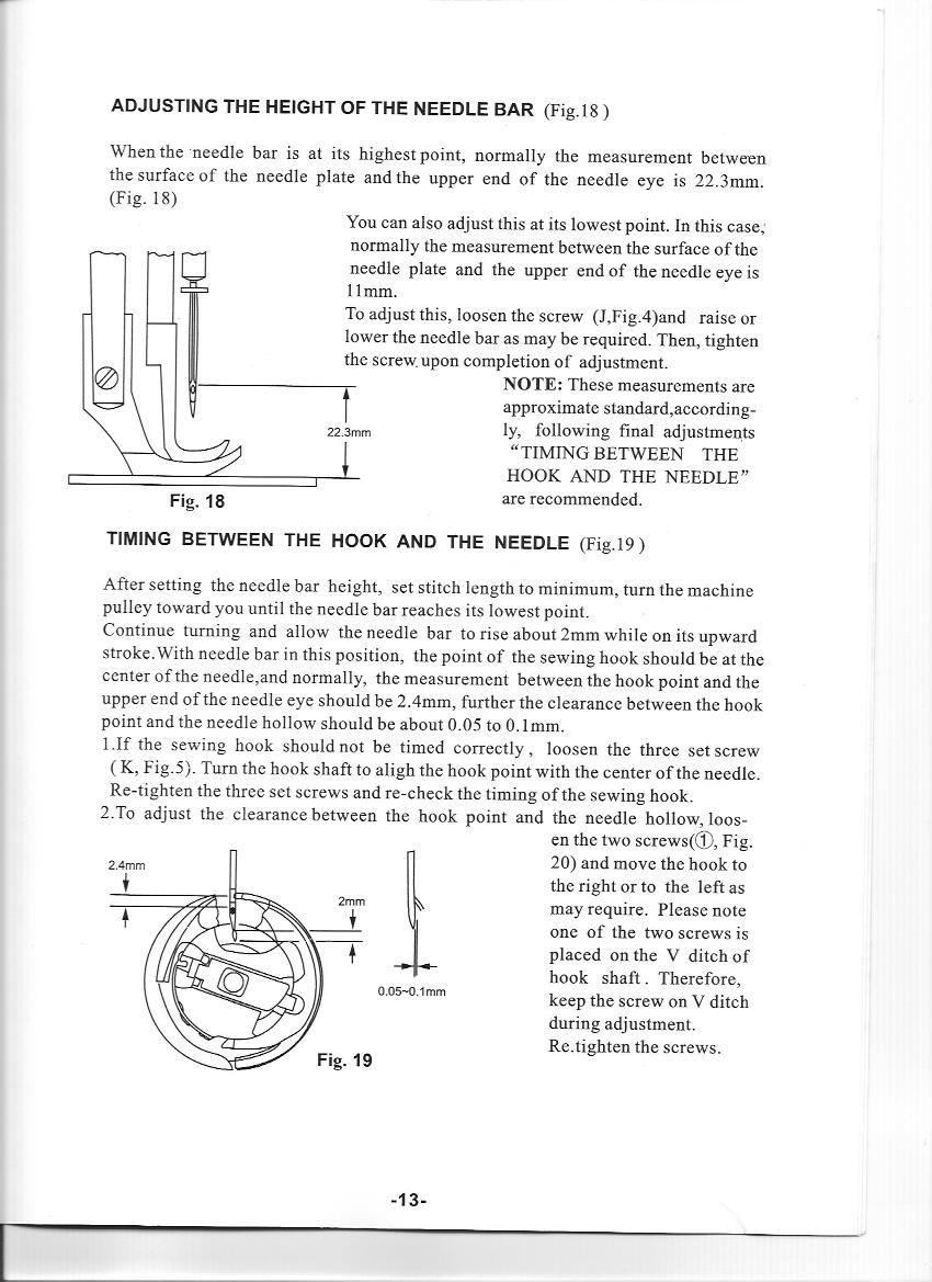
My impression is the needle bar is too high at the point the hook rotates past the needle...sort of common on other machines if your needle has had an impact with something solid. If you have the manual for the 206rb5, page 13 and 14 pretty much line out the procedures for verifying or recovering the correct adjustments. -DC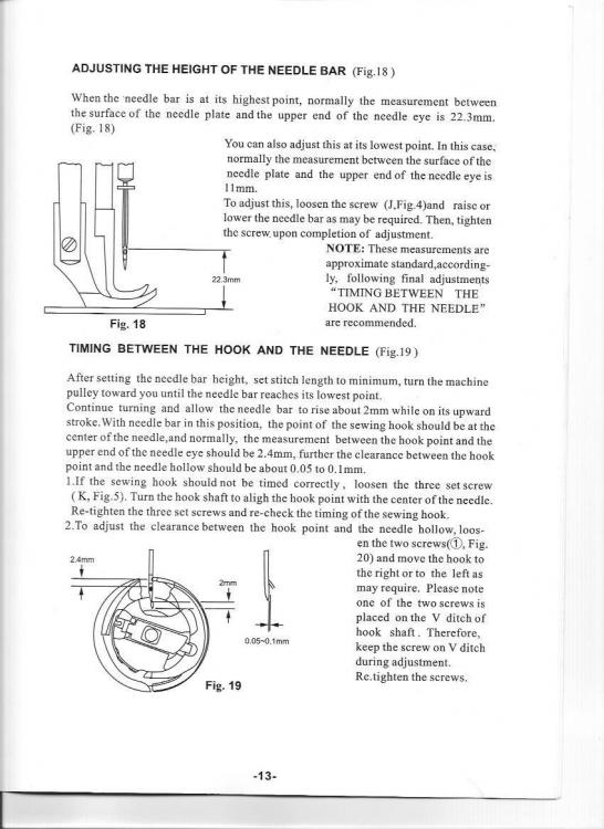
-
Consew 206RB-5: Not picking up bobbin thread
SARK9 replied to MtlBiker's topic in Leather Sewing Machines
Around these parts, its: 1. Working on other machines, getting distracted, and threading the needle right-to-left 2. Not noticing the needle is installed backwards. 3.Make sure the safety clutch didn't trip out.... 4. Aftermarket bobbin cases. IF you have had the hook out, and the simple stuff all checks good, you probably can't get out of double checking your hook timing and needle position by the numbers. Mine has always been extremely forgiving. It DOES prefer that you insert the bobbin case when the dot on the handwheel is aligned with the dot in the main casting. The 206RB5 was promoted as a machine you could just pop a new bobbin in and start sewing, without the usual ritual of drawing the bobbin thread up first with the needle, so yours should be as forgiving as mine if its all healthy. Habit occasionally forces me to draw it up and hold back the needle thread tail for a couple of stitches anyway, just because. -DC -
Binding tighter *inside curves* easily with an inline binder requires some arcane incantations I never was taught, I suppose. The 90 degree makes it way easier. I suppose doing enough faceplants attempting it with an inline binder makes my 90 degree cure a sort of personal preference. LOL. -DC
-
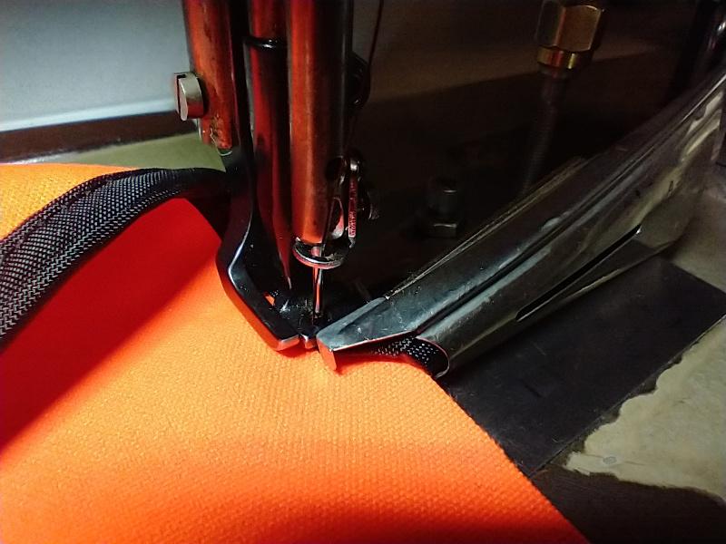
I use the generic double-fold 90-deg. binders (which are SOLD for use on flatbeds) mounted to the bobbin cover plate. This combination WAS mounted on my 111w152 but is now on a rebadged LU-562. As you can see, the needle just can't be much closer to the finished work exiting from the back of the folder. I have the synchronous binder stuff available on my CU-865 Mitsubishi cylinder arm, and it works pretty well, but I really can't see much advantage to it unless the work has a 3-D curved shape and won't lay properly if sewn flattened out. -DC
-
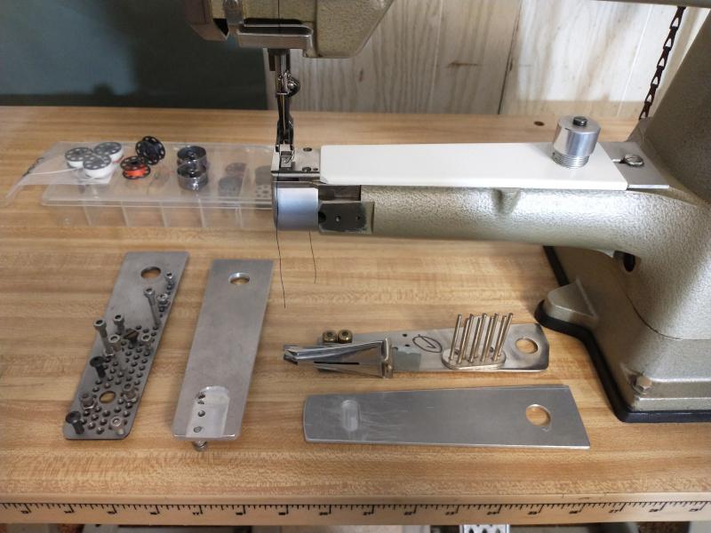
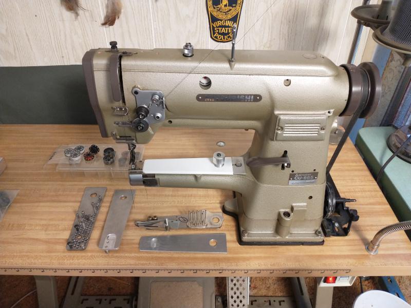
The Mitsubishi CU-865-22 is a very similar (Japan made) machine, and its arm assembly seems to be copied from the "old casting" Pfaff 335 mechanically. There are quite a few clones of this very popular small cylinder arm machine out in the wild. I have used a couple of the generic 335 -style synchro arm covers (sold on Ebay & elsewhere), and they seem to fit fairly well. To change from a fixed arm cover to the synchro, you do have to replace the needle plate, feed dog, and presser feet to allow the parts to mount in the correct proximity for the binder to do an acceptable job. The photo you show with a "flatbed attachment" doesn't have the pivot point "axle" for the synchro arm cover to swing from, but that may be removable on the Seiko models. On my Mistubishi, when I change from a synchro arm cover to a stationary plate, I use a DIY version that has a relief milled in the underside to allow the feed dog driving arm to move back-and-forth normally, yet has no open hole in the upper surface to snag some of the odd work pieces I make sometimes. The pivot point in the arms I use still have the hole for the spring loaded retainer, which I use for mounting and locating aids. I've made up several fixture plates with different configurations to allow experimental setups for different guides and binders.....mostly I adapt the "double fold" binders to my machine because the color choices for tape or webbing are pretty limited. -DC
-
Lots of popular machines use the "U" style bobbin....searching for *bobbins Juki LU-563* will pop some up. https://www.ebay.com/itm/Cutex-Pack-of-25-Juki-LU-1508N-LU-1560N-LU-563-Metal-Bobbins-With-Storage-Case/164249790612?hash=item263e0ce894:g:xHMAAOSwVVBe6phJ ...as an example. -DC
-
Abracadabra! -DC
-
We have actually covered this old saw several times. There are multiple ways to retain the usual "tilt back" when using a wheel-type reducer. One universal rule is to mount the reducer so that its axle's rotation point is very slightly behind the hinge pin location on your machine. This unloads the belt upon tilt and everything is business as usual. I have had a variety of machines all using reducers with brushless motors and still have 4 set up that way now. Carry on. -DC
-
As far as I know, the "old casting" Pfaff 335 feed dogs and needle plates interchange with the CU-865....they are all over Ebay etc. You need to know if your's has the parts for the synchro binder or the regular feed setup. The presser feet are the ubiquitous Singer 111W type walking foot style. Zillions. My upper thread guide is factory stock but looks different than the one in the parts books....mine is a simple straight rod with the typical 90 degree offset holes for the thread to pass through....just a short section of threads on the lower end secured with a jam nut. The knurled nut.....ummm...here's the thread control ass'by. Maybe pick a number? -DC

-
Which parts? -DC
-
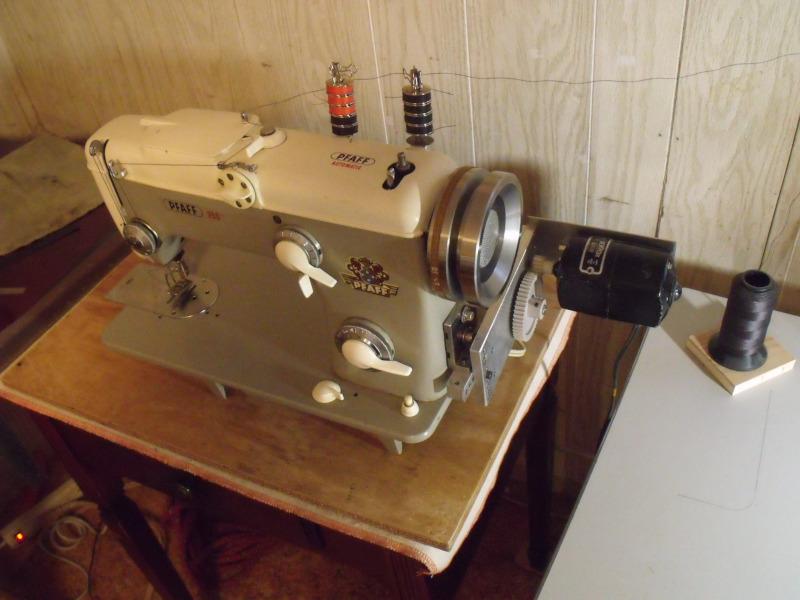
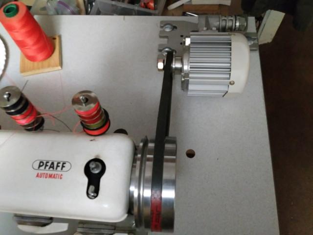
servo motor on vintage domestic sewing machine
SARK9 replied to Mike124's topic in Leather Sewing Machines
Short answer- The main good which will come from this approach is: You will already have purchased the servo motor you will want later in your hand. You'll have to come up with a way to adapt the handwheel to a 3L V-belt to take advantage of the added power.....see below. While the Mira is one of the better domestics and uses the "high shank" presser foot, the feed/transport and presser foot spring are going to be the next weakest link and will always make professional workmanship a risky proposition. I've done something similar to an old Pfaff 260 which had a 'sploded motor and the dreaded *stapled fabric motor belt disintegration syndrome*... both motor and belt are pretty much unique to this model and at the time, were pretty dang scarce and $$$. I turned a nice steel "universal" handwheel pulley for it, which had a groove which would still accommodate the "stock" motor belt in the correct position inside the top cover, but also had a groove for the common 3/16" domestic V-belt, PLUS I machined a groove for a standard 3L motor belt located outboard. I set up a motor mount to use a 1.5 amp domestic motor I had laying around and a reduction gear driving the tiny motor pulley these machines use. It worked pretty well for what I needed it to do, which was attach a heavy fabric reflective panel to a K9 vest made of 1000D Cordura with a narrow zig-zag stich around the border. I later attached a Consew brushless CSM 1000 "servo" motor (with the remote mountable control lever) to it, which was dead easy to do, and it worked well, but then bought a like-new Singer 20U33 and rendered it all silly. -DC