


RockyAussie
-
Posts
3,265 -
Joined
-
Last visited
Content Type
Profiles
Forums
Events
Blogs
Gallery
Store
Everything posted by RockyAussie
-

SLC.. why have thou opened this can of worms
RockyAussie replied to JerseyFirefighter's topic in Leather Tools
@TonySFLDLTHR WOW I love the cutting action on that device. Can I ask are the blades easy to sharpen or replace. Are they small special circular blades or like a Stanley or razor blade set up? Will it be possible to buy just the cutting device with out the other frame work. Being in Oz would be a killer on the frame shipping cost. -
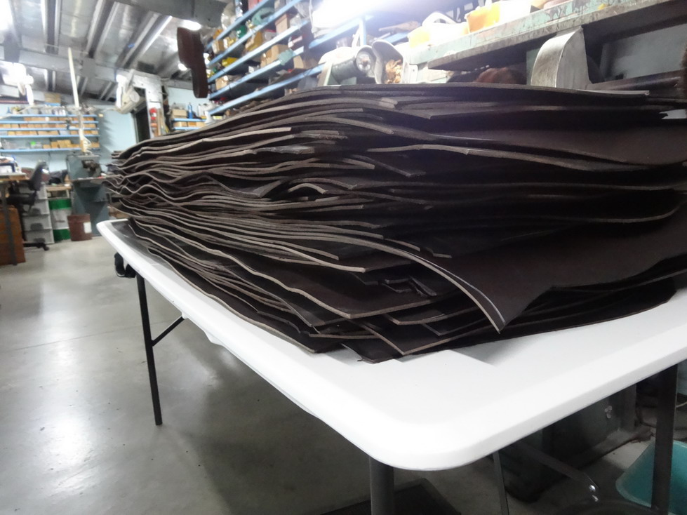
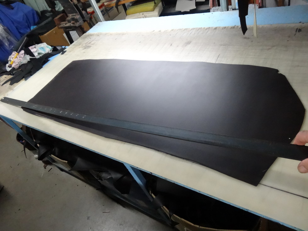
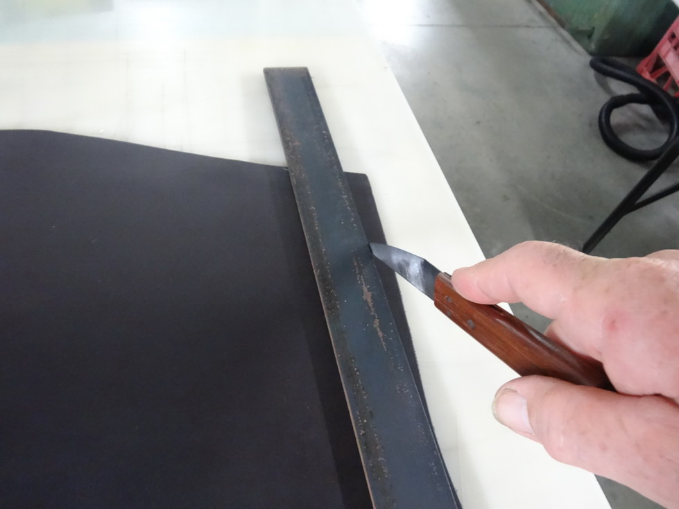
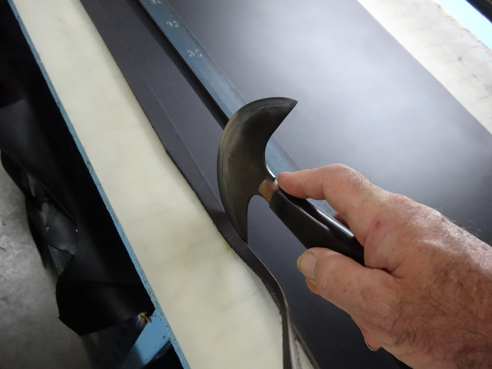
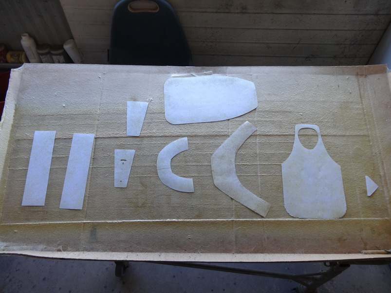
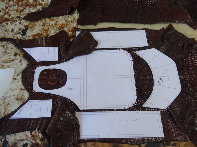
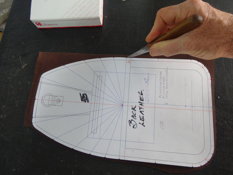
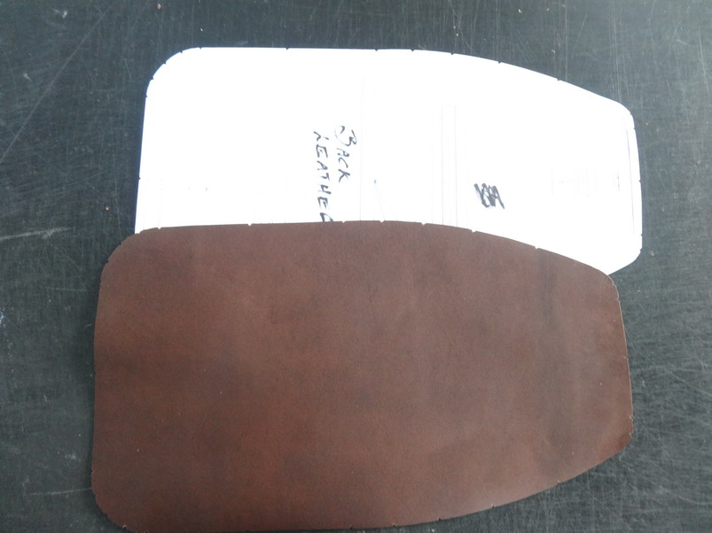
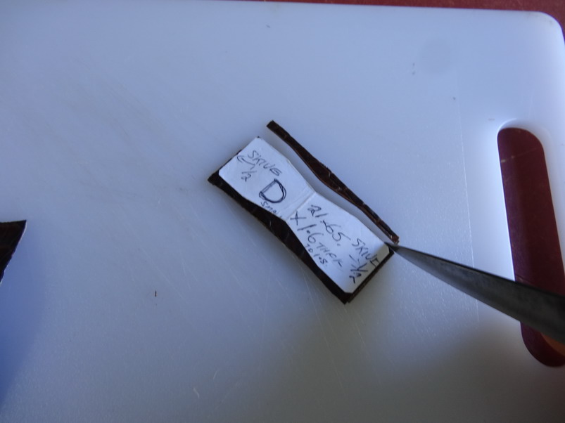
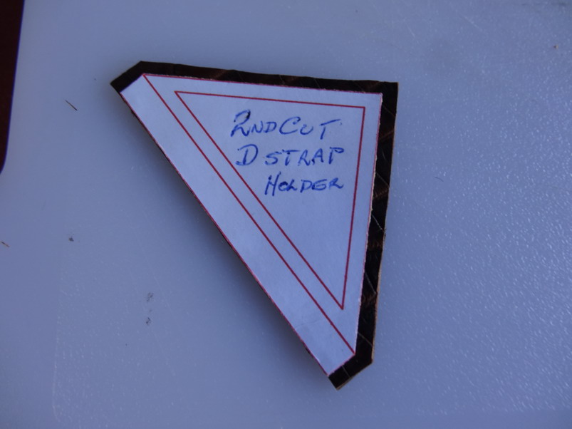
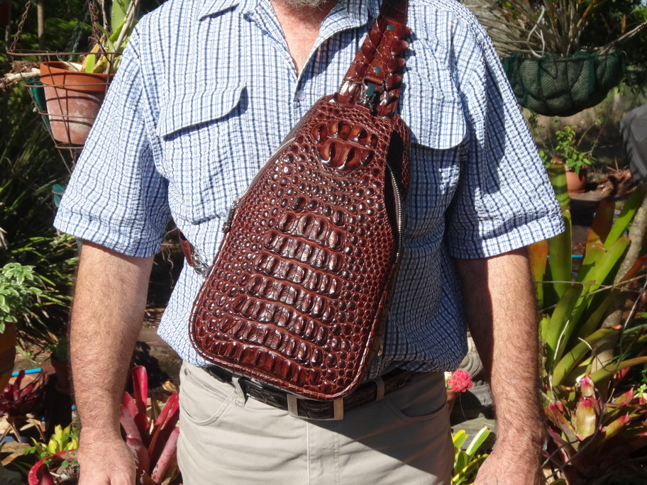
The best way to get straight cuts so far other than perhaps a laser I do as below. This shows a 100 shoulders to be straighten up to then run through a belt strip cutting machine. Here I use a 1+1/2" x 1/4" piece of flat steel which I screw down to the table on one end and put a nail at the other end at the back behind the steel so I do not have to worry about it sliding away as I cut. I lift the steel and slide the leather under and drop it down again to cut. Note that there is a niko line under that shows me where the leather has to go past for cutting. The steel is flexible enough to follow and table irregularities. With the back side of a sharp tipped knife I deeply scribe where I want to cut and then I position the steel back for the main cut. The steel weight helps to keep the leather still as well. Here I like to use my round knife due to its edge holding up for generally most of the job. note at this stage I assist the cut by gently pulling the waste up and toward me. Yeah I know what you mean. I just generally don't do it. Most of the time I design almost every thing to be first cut oversize and then be second cut when the pieces are attached together. That I normally do with made to shape cutting knives on a clicker press but sometimes by hand as in some of these pictures below. For cutting on a pattern which I normally print onto cardboard I start by printing the sheet and then spray gluing the sheet before cutting it out on my cutting table after the glue has tacked of well. These are often re glued and allowed to track off again before attaching to the leather I want to cut. This picture shows some pieces of a pattern spray glued and drying. Here showing that even on very bumpy croc skin I can have the pattern hold still as I cut it or mark out for first cutting. This one shows a pattern for the back of a bag being cut out. Even on small pieces this method I use . I do hold it with my other hand normally but here I taking the picture with it. This one below does not have the leather fully attached together as it has to have straps in it after the edging gets applied but again the tacky surface helps me cut exactly to size. This is one of the finished bags of the patterns above. I have been trying to find time to post the full break down steps for it for some time but there are a huge amounts of pictures and words to do before that happens. I hope that this is of some help to you and look forward to you posting some of yours in the future. Brian

-
I guess if you have a variable speed motor that would not be an issue. I don't do much with burnishing but I would think about using a brushless servo motor as is now commonly used in the sewing machines. I bought a 550 watt one with all of the stuff associated to mount to a sewing machine here for $119AU (about $80.00USD). With that I can set the fast speed where I want and climb up to that steadily if I use a foot control as well. Could also just mount a turn down knob on a spring to vary the speed on the bench. I do think having a spike that can get inside small areas like crew punch holes would be an advantage especially those big holster ones I see at times. I notice a lot have trouble getting them to look well finished if they do it by hand.
-
Just wondering as I do at times ....if the convex bullet shape end would be better off concave to get inside those little tight areas? Nice looking picture there anyway.
-
A lot of the answers to this would require knowing what amount of rounding of the edges there is and what material such as ply wood or nylon and what distance you can get in to sew as well. If the corners are quite box like you would need extra etc. Is it veg tanned leather? I would try and put in a picture of the shape you want to achieve before doing anything more. This link may help a bit - Somewhere in there you will see a handcuff pouch which is about 1" high and I can give you some more detail on that if needed.
-
Quick change multi directional embossing blocks.
RockyAussie replied to RockyAussie's topic in 3D Printers and Lasers
Mike.........I have to say thanks.... but if my work was as excellent as yours it would not need anything extra to help it sell. -
My First Real Project
RockyAussie replied to Chain's topic in Purses, Wallets, Belts and Miscellaneous Pocket Items
VERY nice for a first real project I must say. I like the thick thread myself and chrisash do you not think that the front closure would need it to balance it out some? -
Quick change multi directional embossing blocks.
RockyAussie replied to RockyAussie's topic in 3D Printers and Lasers
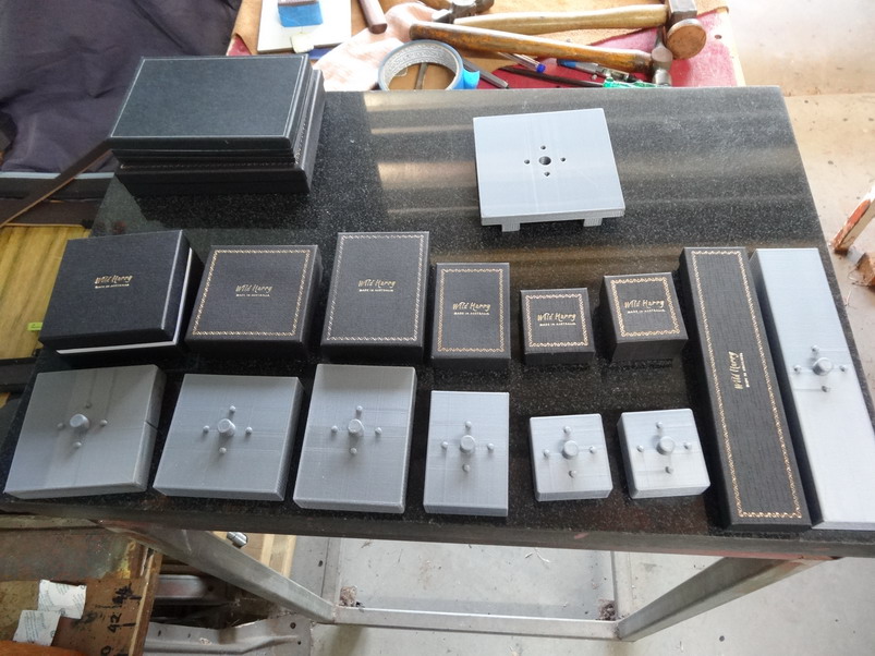
Ok they are done and all in about 2 minutes with swap overs included. Hope that helps some and just ask if need to know any more. Brian

-
Confessions of a leather worker or Why did I do that?
RockyAussie replied to Albob's topic in Leatherwork Conversation
I thought that's what flat surfaces was for........ -
Confessions of a leather worker or Why did I do that?
RockyAussie replied to Albob's topic in Leatherwork Conversation
I will attest to that. A little space is a little to clean up. I have several 8x4' benches that are covered with stuff that to be honest what is underneath I have long forgotten.I sometimes sort of understand why the missus stops...or tries to stop me from building more sheds. -
Sewing machine thread looper for thread stand
RockyAussie replied to RockyAussie's topic in 3D Printers and Lasers
I have only used ABS a couple of times and decided I would master the PLA first instead. For me PLA is much easier but I would like to have the higher heat resistance at times though. I hope to try some of the nylon stuff soon to see how that goes. And the flexable filament types and the ......I need more hours in my days. I wonder if a heat gun would make the warm up faster........... -
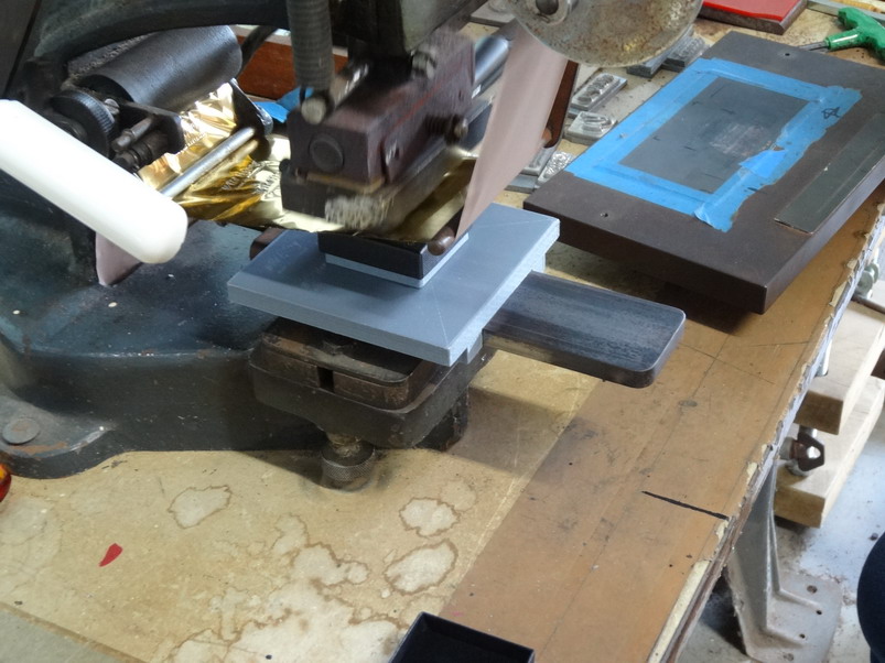
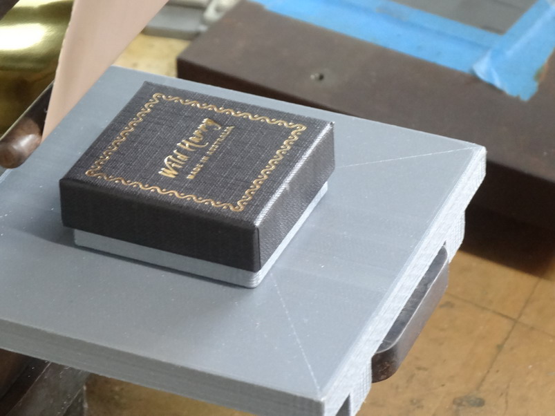
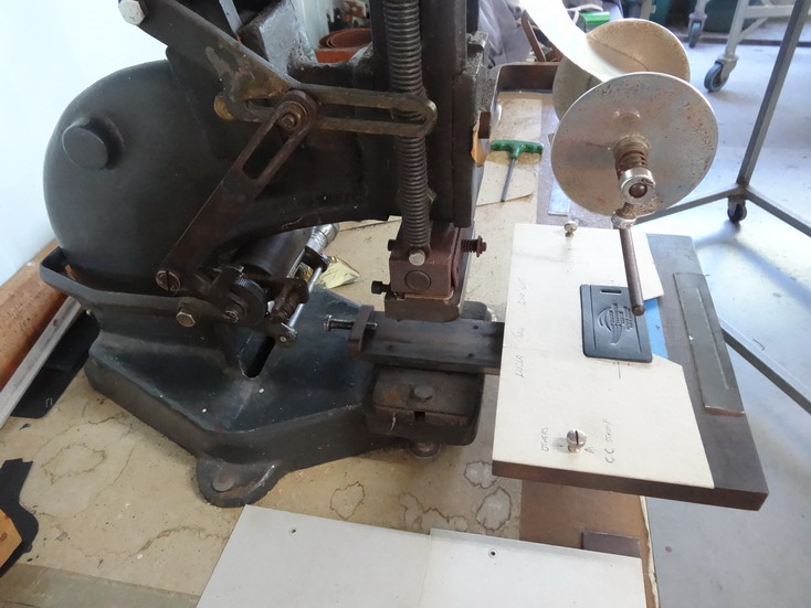
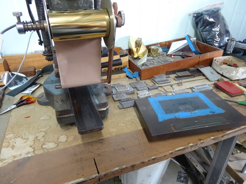
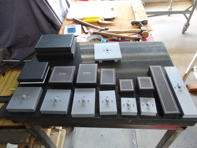
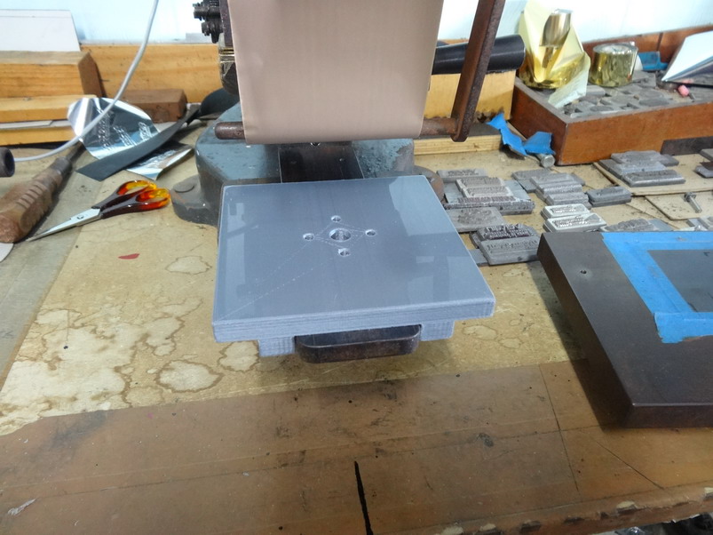
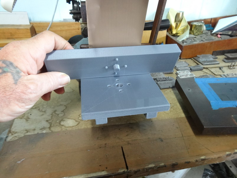
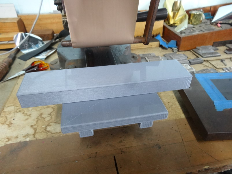
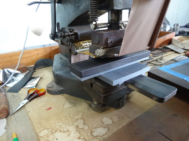
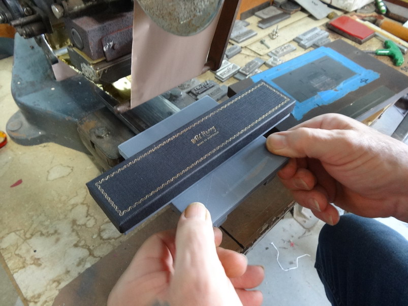
Had a very busy week last week trying to fill a new shop with heaps of our product and of course products need to have boxes. Normally I don't need to send out so many different products in such a short time frame and in the past it would normally take me 5 or 10 minutes or more to set up to stamp these box lids. This is what I came up with and I think the same idea can be applied to most embossing machines one way or the other. Assembled box lids can be a real pain in that they need the platform built up inside the box to press against and to also locate the box in order to have the stamp in the middle of the box sometimes along the box and sometimes across the box. With embossing of different products normally the stamping is done down on the flat and I have many cardboard patterns that get changed over quite quickly by a simple change of screws as shown in this first picture. In the pic above you notice a steel sliding table that allows me to pull the product out and check the quality of the embossing before removing the article from the holding jig. This next pic shows the steel platform removed exposing the slide section underneath. This next pic shows the range of box types I want to now stamp along with their new 3D printed platforms. This picture shows my new slide platform holder that is printed to allow the attaching blocks to be faced in either direction. This first one is for the long pen case. Worked good so next I simply pull out the block and go to the next size. I worked out ahead to make all the blocks the same height in order to not have to adjust pressure settings in between. In the drawing process I should add that once I worked out the location pegs and the centre one I just copied the same along into each block. After that each block took about 2 minutes to draw and save to STL files. I should also say that it is best to put in your tweak setting to slow to half speed when the pegs are about to start. I will post a couple of more pictures to finish off shortly.
-
Sewing machine thread looper for thread stand
RockyAussie replied to RockyAussie's topic in 3D Printers and Lasers
Looks pretty good there @dikman I am thinking about doing it now. If that filament is from the same mob I mentioned I had a bad roll awhile back and I sent them my fail pictures and they were quite happy to send me some new stuff which worked good. I did not have to return the other crap. I think it should work out fine but let me know. -
Sewing machine thread looper for thread stand
RockyAussie replied to RockyAussie's topic in 3D Printers and Lasers
Yea I thought about that as well but there is a hole in my stand on the top that is a good resting space for it and I just hope I can remember where that is when I want. Funny how things can be right there in front of you and you cant see it at times. I was looking for my glasses the other day and couldn't find them until I took them off to see that would help me see any better........... -
Sewing machine thread looper for thread stand
RockyAussie replied to RockyAussie's topic in 3D Printers and Lasers
Yeaah look to the left now....1000 posts and 4 dots above -
Sewing machine thread looper for thread stand
RockyAussie replied to RockyAussie's topic in 3D Printers and Lasers
How about if I post you a few with some zip guides etc and you pass some on to others over your side? 500 gram express is about $11.00. Way more than the product value. I cover this time if you want to pm me an address. -
Sewing machine thread looper for thread stand
RockyAussie replied to RockyAussie's topic in 3D Printers and Lasers
I don't know about that I got a pretty good missus but I have heard they are printing food stuff these days and houses as wel, Interesting. I think you are about to be a 4 star member..... -
Sewing machine thread looper for thread stand
RockyAussie replied to RockyAussie's topic in 3D Printers and Lasers
I mentioned above the pla filament being PLA+ from 3D Fillies being 10 times stronger than regular pla. Here is a link https://3dfillies.com/?gclid=CjwKCAjwzqPcBRAnEiwAzKRgSxhTk4htbykpLdkqAzxdBW0AE2JEs7o3NqimPslmJhQV0Qmm-uoqCRoCKX0QAvD_BwE They appear to have a broad range of other useful filaments as well like pla with steel for your average printer as well. -
Sewing machine thread looper for thread stand
RockyAussie replied to RockyAussie's topic in Leather Sewing Machines
Yea... having a bad back inspires me quite a bit at times. Now I'm gonna have to print a straw holder attachment for me coffee cup. Wrong section I know but if you haven't tried them out check these 3d Fillies filaments. https://3dfillies.com/?gclid=CjwKCAjwzqPcBRAnEiwAzKRgSxhTk4htbykpLdkqAzxdBW0AE2JEs7o3NqimPslmJhQV0Qmm-uoqCRoCKX0QAvD_BwE Not only 10 times stronger pla (PLA+) but pla with steel as well. I am going to get some of that flexible filament and have a play with it soon. I can see a whole lot of potential uses with that. Vibration dampened parts,flexible zip guides and so on. -
Sewing machine thread looper for thread stand
RockyAussie replied to RockyAussie's topic in Leather Sewing Machines
I had not heard of a serger looper before and looked it up and some of that sort of thing could work I think. Trouble here is Rockhampton the town is not that big and the 1hour drive in and out and the unknown amount of hours searching for something that's probably not there, was not worth it. The needle threader I don't have either but would be not much help for my back if I did. The time to print is pretty slow at 11 minutes and at a cost of 7 cents (1 Gram of filament)and the drawing took about 10 minutes. I have been using a bit of twisted wire but I don't like the way it scratches up the hole when it gets pulled in and out. Mostly I just like to share something here if I think it can be of help to them. The coffee splatter ....I didn't see it when I took the picture just later and I just thought bugger it that will have to do. Good thing now I have a few printed so I wont have and trouble finding them. -
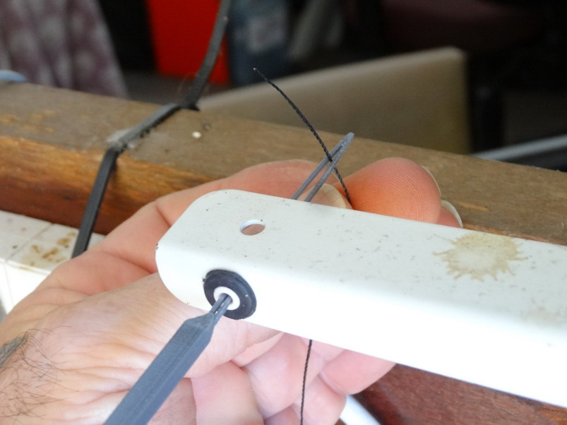
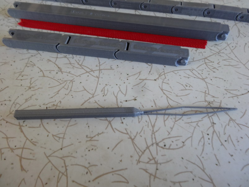
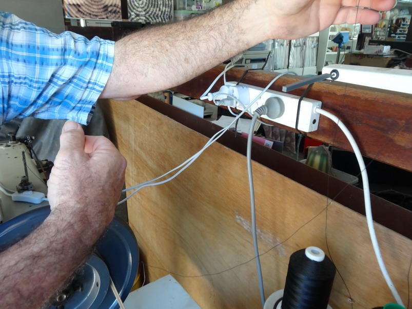
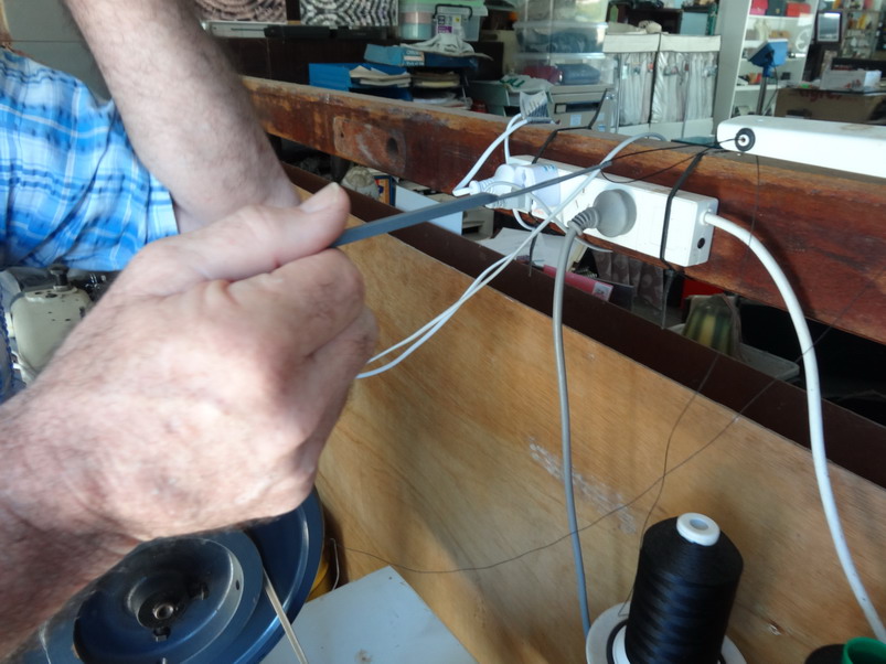
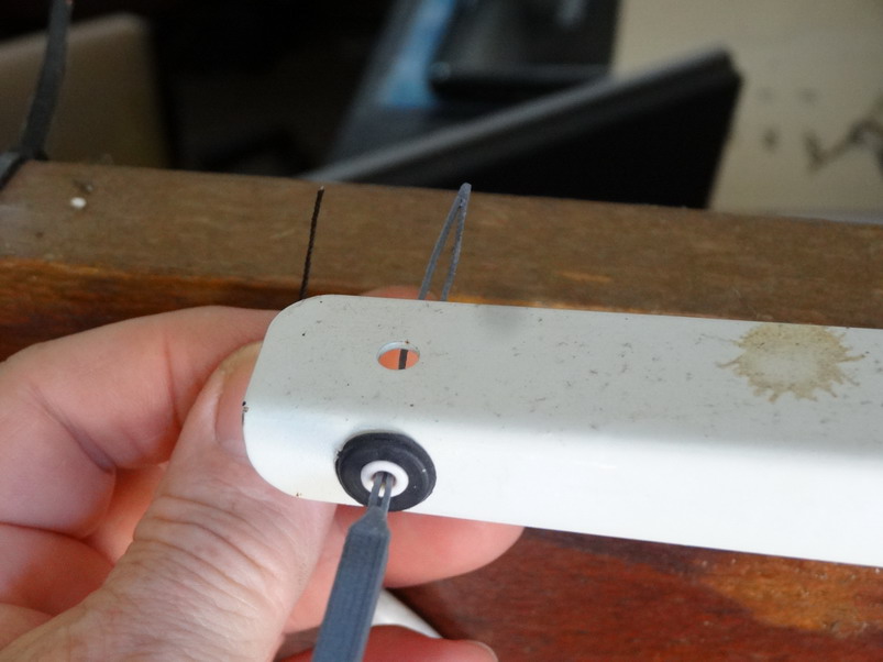
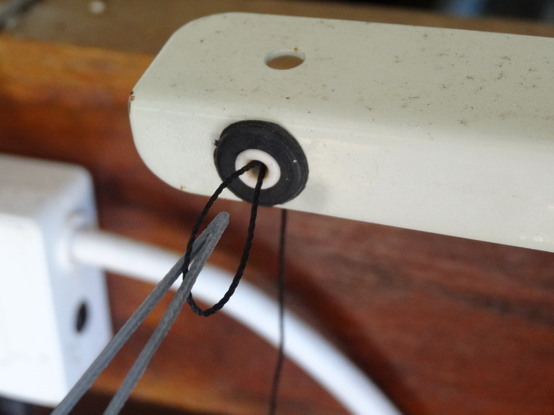
For anyone having a thread stand on the back of their sewing machines and it has a small hole this may be of interest. Check out the link here- For those that do not have available 3D machines I am interested to hear from anyone who could be a distributor for the finished products as shown below in their country. A few people have asked me about purchasing the zip guides and I would like to do it if it can be affordable and fair. These guides have been refined (lower profile and smoother finish) since my last post here and are now near ready to roll. Mostly I am looking at how to cut down postage costs to each country as that is more than the product costs from here in Australia.
-
I hate reaching over and trying to poke the thread through the tiny 2mm hole in my cowboy machine thread stand so here is what I came up with. Don't know what you would call it so let me know if you do. The first pic shows the finished tool. Note that this is printed with PLA+ which is supposed to be 10 times stronger than PLA. (3D Fillies) Next position the tool in the thread hole Grab your thread Poke it in the tool slot Now pull the tool back out of the hole For those that would like to print it I had one leg not print out the first time. Although it looks to be there in Curra it did not show up in the G code. I should have checked the layers veiw as it shows up there. I found I had to rotate it on the plate a couple of times to get a direction to where it all showed up in the layers. I double checked the G file and Bingo it worked. Here is the stl file - Thread stand loop toolS.stl Forgot to add I have embedded Made in Australia into the base if that's a big deal. That's it for now Brian

-
Walking foot with synchronized binder
RockyAussie replied to talon's topic in Leather Sewing Machines
I have seen plenty of cheap conversion kits out of China for converting a 335 style machine into a synchronised binder but not the other way around. I would think about getting a 335 with the moving dog foot and then converting if needed. From memory the cost was less than $100 and I can dig that out if you want to have a look further. -
Congrats @bikermutt07
-
Hi Garry, I did not know if it would be as stable as I wanted and that is 1 reason that I wanted it hollow inside so I could fill it with sand if needed. I Thought about printing it with a hole for that purpose but decided it would be easy to just drill a hole in the base and fill it and seal it later. You can pause the print and add components like nuts and so on but with the weight to add ballast the table on my old antique printer would have to be throwing that around as well .....not a good idea. Some printers operate from up at the head only in X and Y directions and they should have no worries like that. Conclusion is that I think its more than stable enough without the sand. I work really hard so one day I can be lazy and I enjoy designing stuff to make my life easier. Plus when designing I get to sit on my but awhile. Thankfully my missus doesn't read this forum