


RockyAussie
-
Posts
3,265 -
Joined
-
Last visited
Content Type
Profiles
Forums
Events
Blogs
Gallery
Store
Everything posted by RockyAussie
-
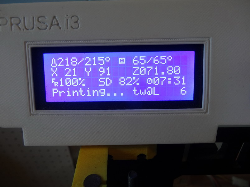
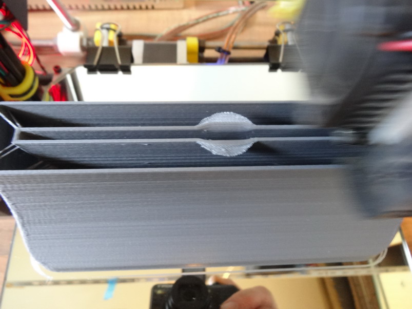
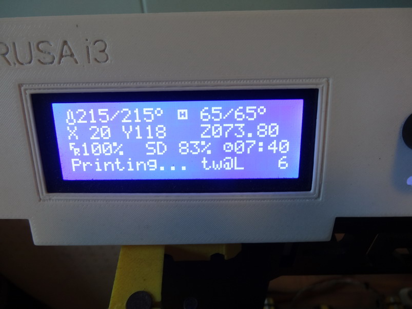
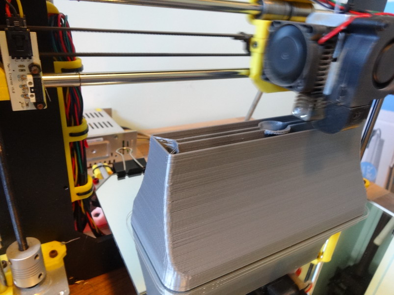
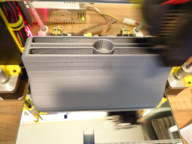
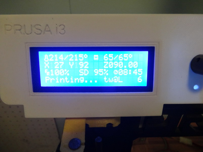
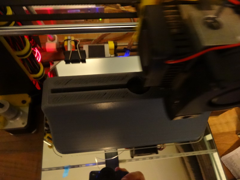
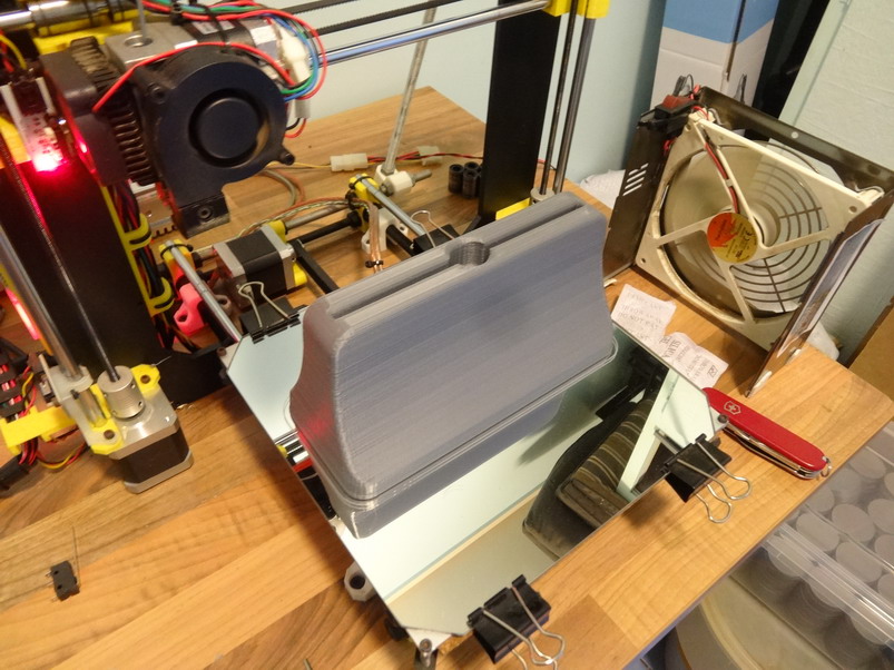
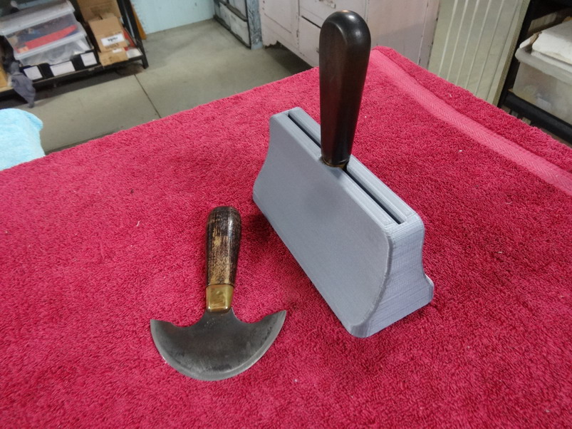
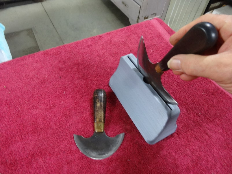
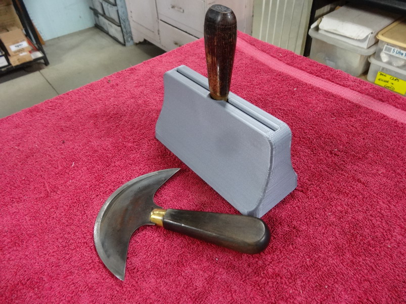
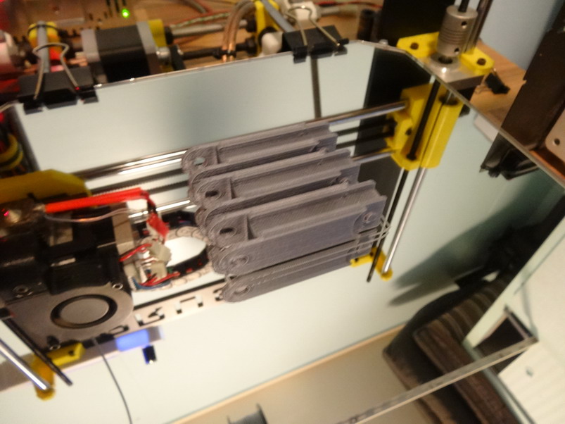
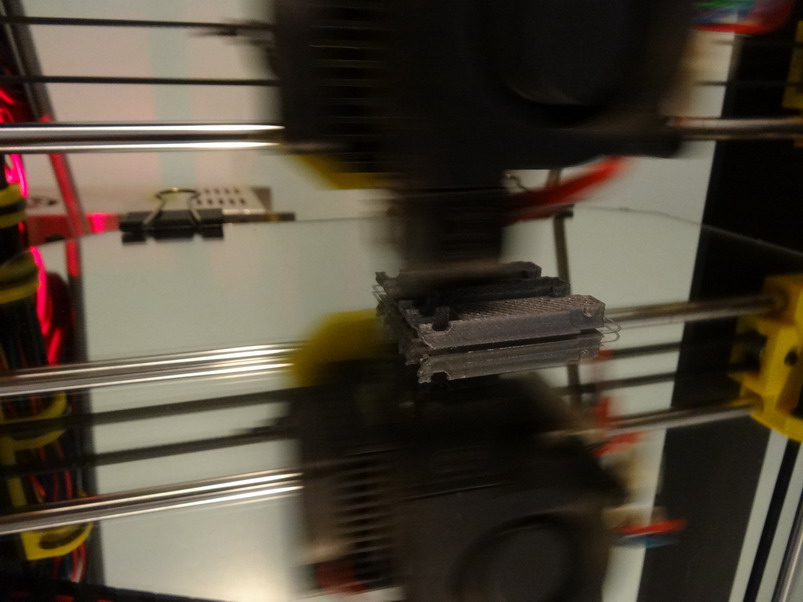
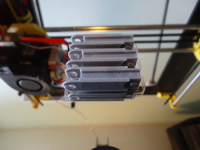
For some time when using my head knives I have wanted a stand up holster/stand to put it in safely between the repetitive using of them. Its a long print job but for me it is worth it at least. Here is the stl file - HEAD KNIFE HOLDER.stl You will need to lay it as shown in the below pictures. To try and save print time I have drawn it with a hole in the base to act as a support. This way in Curra I have given it No fill. Here is an extract of the settings I used. M190 S65.000000 (BED TEMPERATURE) M109 S215.000000 (NOZZLE TEMPERATURE) ; -- START GCODE -- ;Sliced at: Sat 25-08-2018 19:34:19 ;Basic settings: Layer height: 0.2mm ; Walls: 1.2mm ; Top and Bottom: 1.6mm ; Fill: 0 percent ;Print speed: 60 ;Print time: 9 hours 18 minutes ;Filament used: 49.55m 146.0g ;Filament cost: 5.41 The first pic here shows the bottom layer near done Now showing the shell style print At this stage the print has started the blade curve This shows the point at 71.8mm high where to watch for any filament colapse as it is starting the bottom of the knife feral support. A 6" knife will not touch the walls if located in the centre hole. The top is now starting to connect At this stage the print in the air starts.....No problems found. First layer over the air done. Yippie ...success Here showing the large 6" head knife comfortably housed Now showing the smaller Osborne knife that has a wider feral. It sits in nicely as well. That's it all I think @YinTx inspired me with this. If I recall I was trying to explain the new Taco shell shape. Brian

-
Zipper installation multipurpose guide
RockyAussie replied to RockyAussie's topic in 3D Printers and Lasers
WOW that is very close to the stated 6mm.Spot on with my measurement above. I think the No 5 link should work well but I will do up one on 99% and 101% as well and try them out. PM me a place to send I will try and get you some somehow to try out. Note: On the No 5 stl here I made for the nylon coil .....it works great but I found after a couple of days and little shrink back it is now not tight enough for the metal No 5 to hold it tightly. Fine for glue line up but not for straight to the sewing machine. I have been measuring for a few days now and so far no more shrinkage but means I will have to try one for the metal at a lesser percentage. I will let you know sometime later this week. -
Zipper installation multipurpose guide
RockyAussie replied to RockyAussie's topic in 3D Printers and Lasers
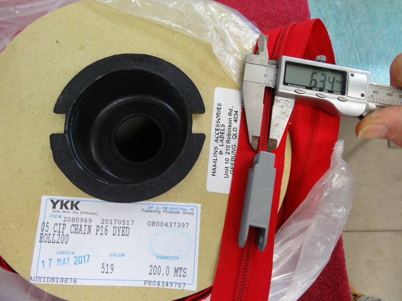
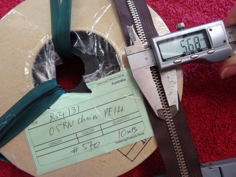
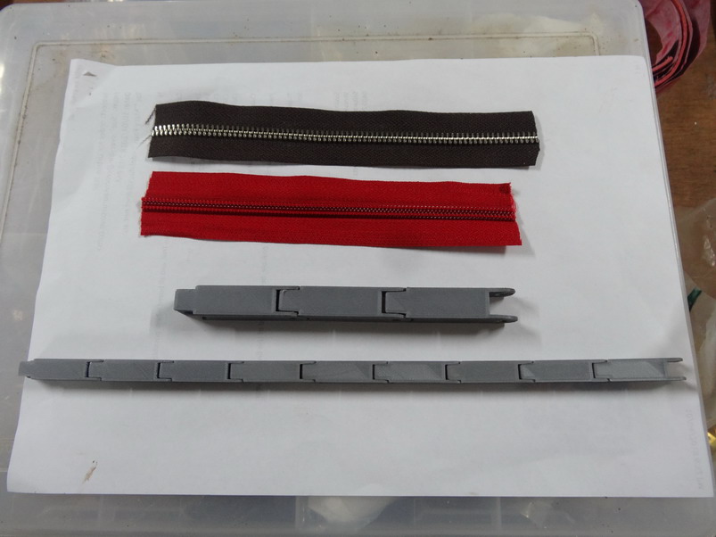
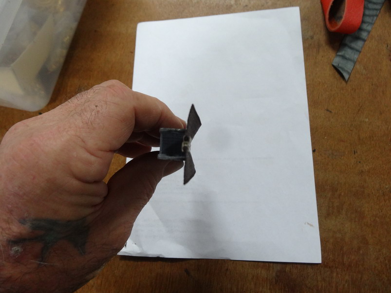
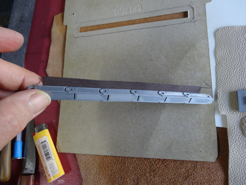
Can I ask if you have checked the width of the teeth with vernier callipers as in my pictures below. If so and that is correct I could do a few scaled size pieces and send 1 of each for you to let me know which ones fit best or you could send me a bit of each if you prefer. P.M. me the info if you like. Hi Wizcrafts, I went and checked my measuring all over again and went online to double check again and a #5 YKK is not 5mm wide and I have put in a link from a couple of sites that give a closer idea to the measurements. Sailrit says #5 is 6.35mm - https://www.sailrite.com/Choosing-a-Replacement-Zipper-Slider SBS Zipper has a bigger detail chart and confirms similar measurements to mine - http://www.sbs-zipper.com/blog/standard-zipper-sizeteeth-width-specification-charts/ I have an upholstery friend in town and I will try and get a few other size zippers from him as soon as I can and get back with the info. Here is my measurements of #5 coil This is on the metal #5 Here showing the guide measurement I've supplied the stl file for here. These work well enough for my use and I would suggest that if anyone finds theirs a little tight or loose they need only scale it up or down a percentage to get it right. I have not done any on the thicker plastic zippers yet and they would likely need a deeper depth of hole which would not work with scaling. If anyone wants to send me any zipper pieces to make a suitable stl file for let me know. Brian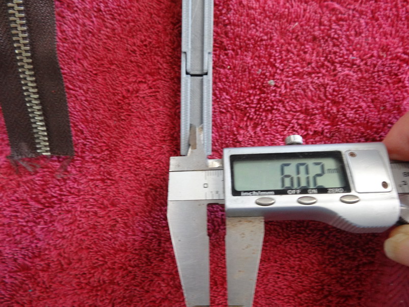
-
Zipper installation multipurpose guide
RockyAussie replied to RockyAussie's topic in 3D Printers and Lasers
Well done ....I wonder if your gap between nozzle and the plate might be a little wide. I have some zipping spare here if you want to try sometime.
-
Zipper installation multipurpose guide
RockyAussie replied to RockyAussie's topic in 3D Printers and Lasers
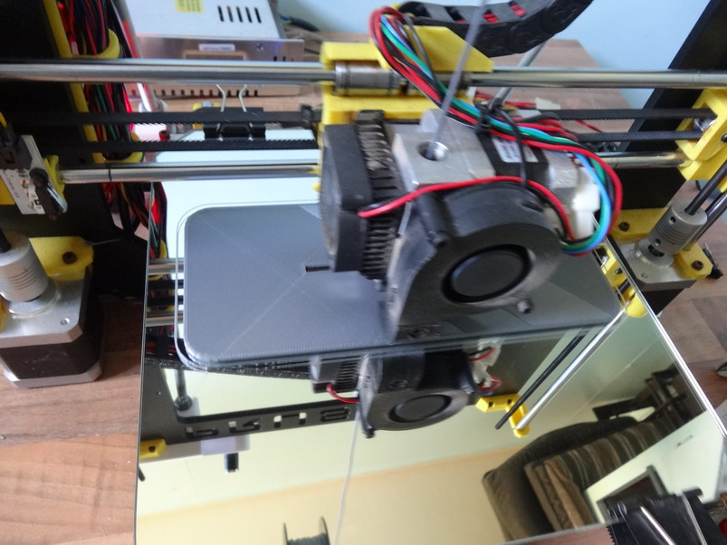
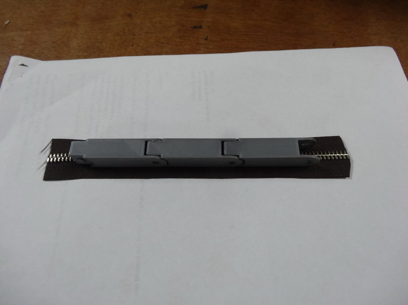
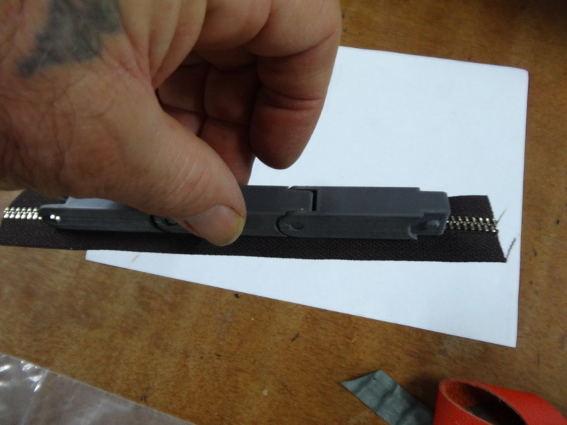
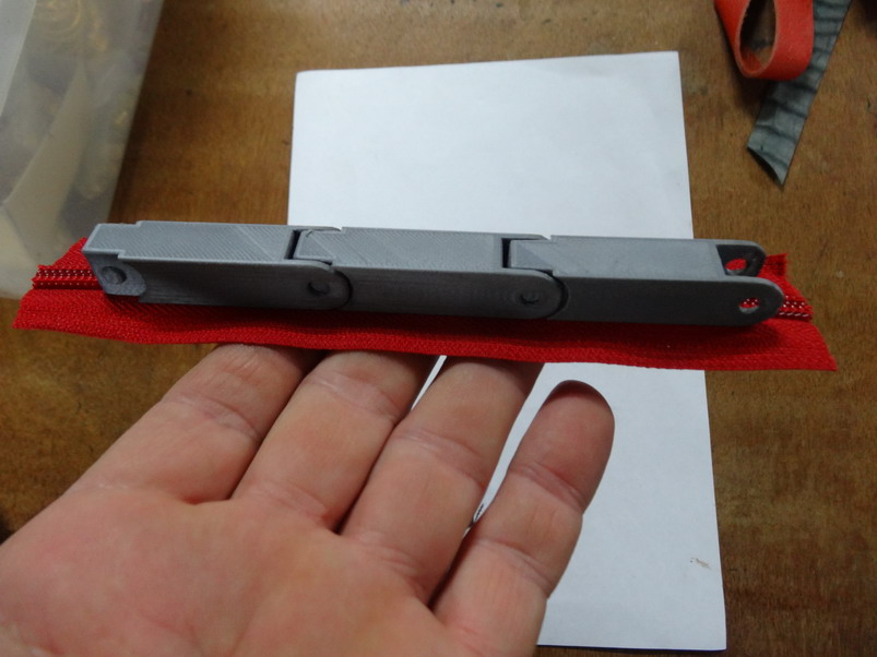
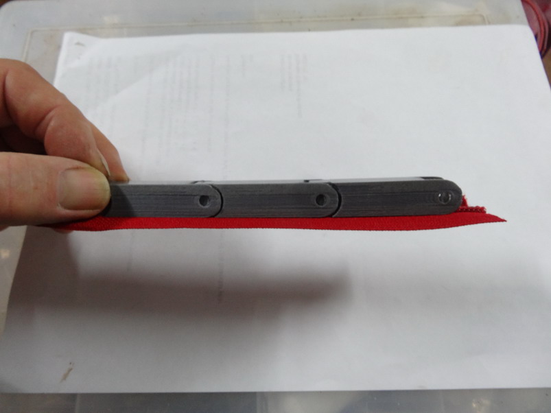
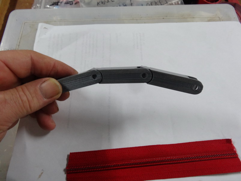
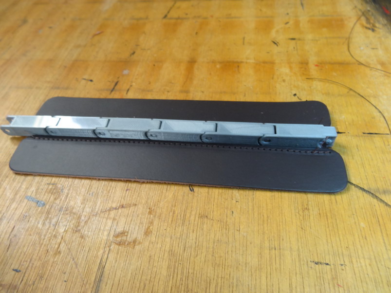
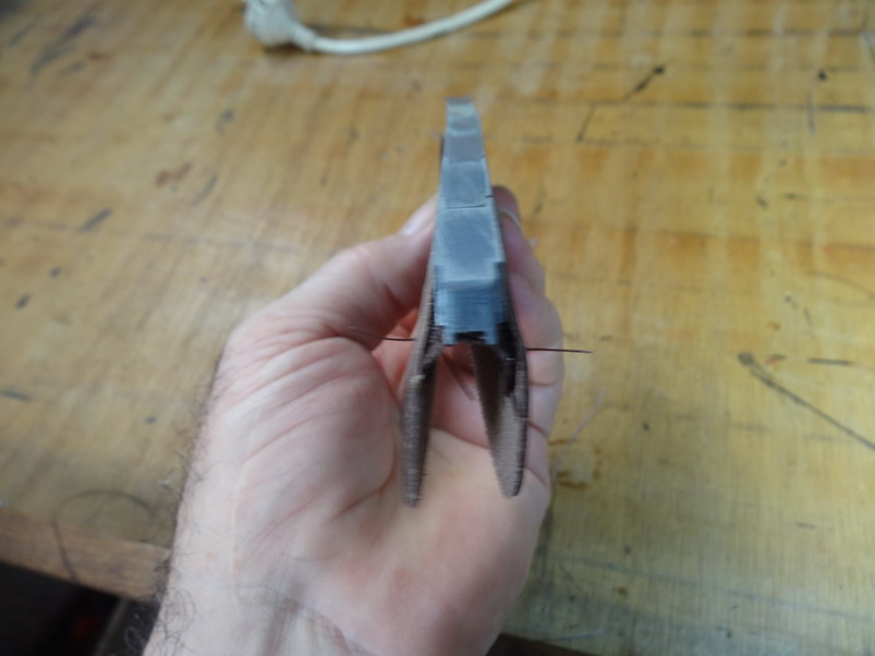
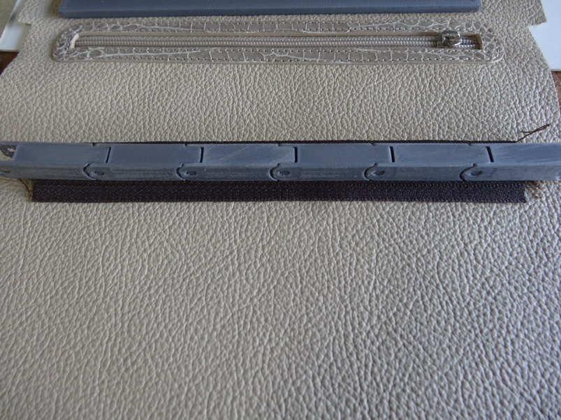
Well here is the guide stl file for the YKK NO 5 nylon and as it turns out metal as well. No 5 YKK zip guide.stl I must admit I cheated a bit here as after some measurements as maths I just scaled the No 3 guide up exactly to 1.5 and this is it. If anyone wants to give me the exact measurements of the width of the teeth done up in mm of any other sizes I will do the stl files for them to test out as well. Here firstly for those that are curious is my old humble but very busy printer. The large fan to the right is just to cool things quicker when the print is finished.The box in the far right bottom corner is the ring box prints which is what keeps the printer busy a lot. This shows the No 5 guide now finished and the orientation I so far recommend. I might try laying them in the Y direction and see if more holes improve any. I tested for sewing foot height on my little cylinder and the big cowboy and no problems but it may be a bit high for some machines......please let me know and by how much less if necessary. Note the height and width is about 1/2". Here I have attached it to a No 5 YKK metal and it is a quite tight push. Note that the back dishes in a little but seems to lay down flat well enough to work alright.You may want to scale it up 1%. I did a back check to make sure that it had not spread too far for the nylon and it was fine. I think I might start a new post in the 3D section that has combination of links of other projects I've posted here over the last couple of years like these below. What do you think?.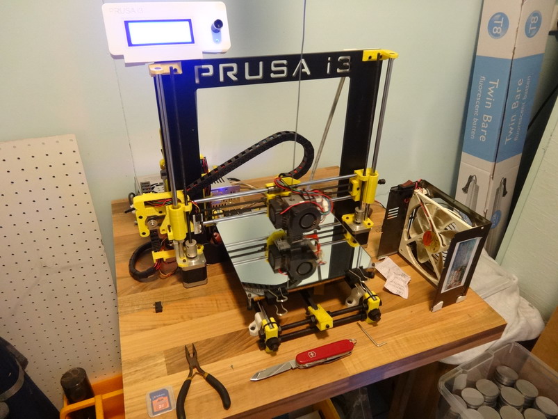
-
Hey I'm thinking that maybe you have just scaled it down and every thing has compressed beyond useful?? Give me the diameter and depth of the bobbin hole and I'll load up an stl if you like. You do want one bobbin hole going right through? Let me know. I am curious why your bottom layer is not connecting and possibly you need to increase the flow from 100 to 103% if it is on the hundred% that is.It could also be that your nozzle is a little bit to far away from the platform. I get it down less than a Tallo-Ho paper if I can and my first layer is always smooth as.
-
Zipper installation multipurpose guide
RockyAussie replied to RockyAussie's topic in 3D Printers and Lasers
Hi Uwe, I have to be quick as dinner is ready. If it holds the zip firmly it will stay quite straight. If not increase you flow a little or as below. The compression on the zip working together should make it straight. M190 S65.000000 That's my bed temperature M109 S215.000000 This is the temperature I'm running the filament at. This is pretty hot but I like it to really connect well. Causes a little swell. Also I have the 1.75mm filament set at 1.74mm to offset variations in the filament thickness and that also increases the size a little but makes for good connection. Another note: I am running a .4mm nozzle. ; -- START GCODE -- ;Sliced at: Sat 18-08-2018 13:00:48 ;Basic settings: Layer height: 0.2mm ; Walls: 0.8mm ; Top and Bottom: 0.8mm ; Fill: 30 percent ;Print speed: 45 ;Print time: 28 minutes (That is for 3 pieces= 9.3mins each and is possibly why your holes look better than mine ;Filament used: 1.747m 5.0g ;Filament cost: 0.19 -
Zipper installation multipurpose guide
RockyAussie replied to RockyAussie's topic in 3D Printers and Lasers
The PLA filament I used in this case is pretty cheap and easy to use. The large rectangle bobbin holder uses 116 grams at 30% fill and that is around $4.00 au (about $3.00US). The revolving bobbin holder at 20% fill is 80 gram which is about $3.00au ($2.25US dollars). You have to take into account a little bit for the power cost etc as well. I just checked the little zipper piece and it is 2 gram and cost 6 cents au. Good thing there as you can load the platform up with heaps. Brian -
Zipper installation multipurpose guide
RockyAussie replied to RockyAussie's topic in 3D Printers and Lasers
Hi Garry, Not quite ...an stl file is just a file that any printer or I think cnc can get the raw information from. A program like I use Curra then converts it into a G code that then is able to tell the printer how you want it to print out. At the stage before you make the G code you can set how fast you want it to print, how many copies you want it to do, how much fill you want it to have. That means it might be 90% hollow if it does not require a lot of strength or fully solid if you wanted it to be a stamp.It can also be scaled higher or wider or longer or just wholly bigger or smaller etc. It also allows what temperature to set the heated nozzle for different type of filament. The filaments come in a wide variety and can be extra hard down to soft and flexible. After the G code is set it is then pretty much plug it in and let it go. Its a little bit like having to learn how to set your tensions and thread paths and needle sizes and which needle brand works best etc but the huge range of things that you could apply this knowledge is almost infinite and already spare parts in cars etc are being replaced with this technology. They are even printing Robots now so learning how to design with it is at least one future that will be here for awhile. Brian -
Zipper installation multipurpose guide
RockyAussie replied to RockyAussie's topic in 3D Printers and Lasers
Straight as we get it it works alright but we do buy drums of thinners as well and thin it to whatever the job requires. For spraying the glue we this it maybe 10%. -
The diameter of the holes is 25mm but you should be able to scale it down in Curra or whatever program when converting the stl to the G code. I will try and get an stl file made for the smaller bobbins sometime this week if you like as I think I like that idea somewhat myself.
-
Zipper installation multipurpose guide
RockyAussie replied to RockyAussie's topic in 3D Printers and Lasers
Good news UWE is going to see how they work on his printer and let us know. I don't have any Riri zippers to measure the teeth width and test but I am sure there would be no problem doing them at all. I will work on getting something for them asap. -
Zipper installation multipurpose guide
RockyAussie replied to RockyAussie's topic in 3D Printers and Lasers
Hi Bill, I saw this one recommended in another post last night which is pretty much plug and play $280 + free postage and they have another I would like that has a 300mm square platform as well. Very tempting....Shame its way over your side of the pond.https://www.monoprice.com/product?p_id=13860 -
Hi Garry, I learnt how to draw up my patterns in Auto cad many years ago and did not know it even did 3D stuff. At first it was a mind bender but really its not that hard when you get used to it. I am by no means a techi type and I tackle most of this in my own very simple way of doing things. Mostly its sort of taking your 2D drawing say a box, and combining it into 1 polyline that is connected all the way around and then raising it (extruding) to whatever height I want. If I want holes in it I make a circle ...extrude it ...put it into the now cube and then you subtract it. Bingo there is now a hole in the cube. Main rule is to put a handle like a line hanging out an inch and another handle off of it going up (Z direction)an inch and make sure you keep copying these along with new changes. This makes it easier to see and give an easy line up location when you put some thing new into the drawing. Lesson Over Brian Yes I'm quite happy with it. It takes up very little space next to the bobbin winder and is handy. Plenty of room for various arrangements to be made. I even considered a bigger lazy Susan style that could have 4 or more of them from a central point but....to me clarity in design is 100 shades of grey turning into 10 shades of colour.
-
Zipper installation multipurpose guide
RockyAussie replied to RockyAussie's topic in 3D Printers and Lasers
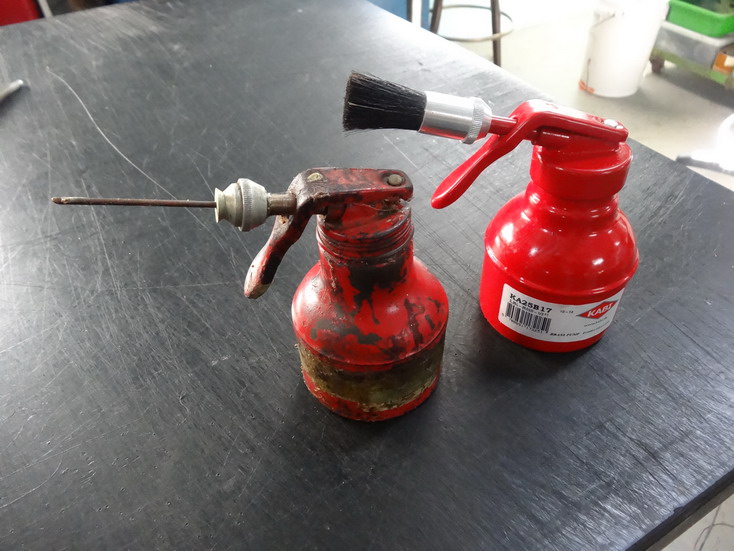
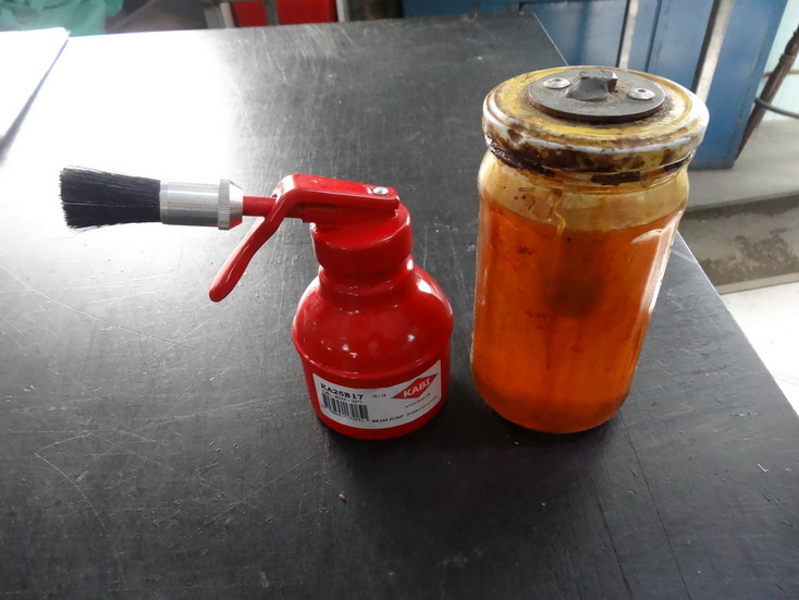
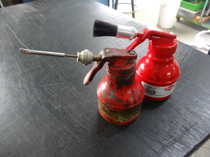
I will do that Wiz as best I can. I would be honoured to send you a range of the different sizes as soon as I can get them done. If you decide to get them done faster mention that the scale part in a program like Curra will allow you to make them as long as you want or short and wider as well for various width zips. I don't know with out checking if the piece is made wider for a number 5 zip if the gap from the stitch would be good or not. It may be fine. Your shop address alright to address to? That is a glue pot that I converted over from being a brush on style. If you want one H. Leffler and sons should have them. I have plenty of old brushes worn out here and I just break away the outer aluminium part that retains the brush and insert a brass tube that you can get at the hobby stores. I cut it to length and flare one end and force it into the hole. I then hammer around the top edge of the aluminium next to the brass tube to really tighten it into place. A little bit of an angle grind to the tip helps the spreading out. I keep the tip from drying out by keeping it covered by a bigger tube that I have the end squeezed shut on. The one in the picture is a bit of brake tubing. A bottle made up with a bolt inserted as shown helps to keep a swap over tip or brush ready to This pic shows the brake tube cover Another handy thing to store multiple brushes in thinners is a army food dish. As to the glue (NE - 1820) I buy it from a chemical company in Sydney (PCA Barham pty ltd) in 20 litter drums but your local shoe repairer should be of help. Its just a contact glue. Freight is a killer to get it here. Brian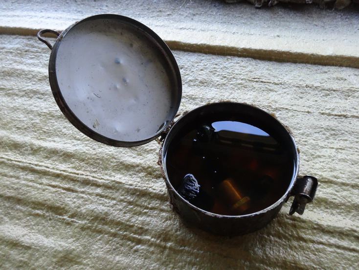
-
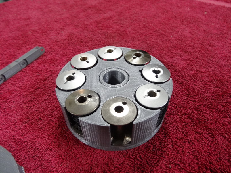
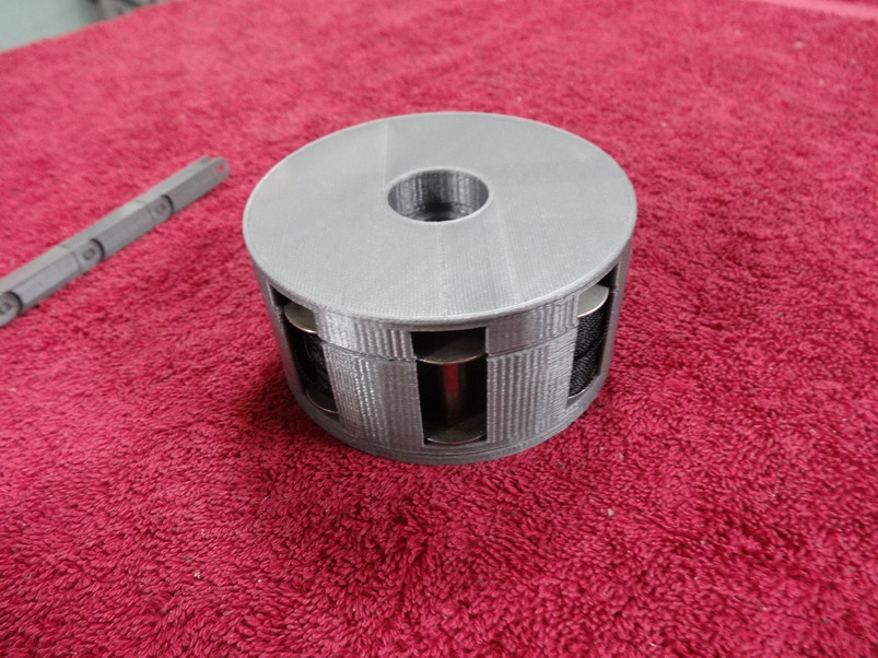
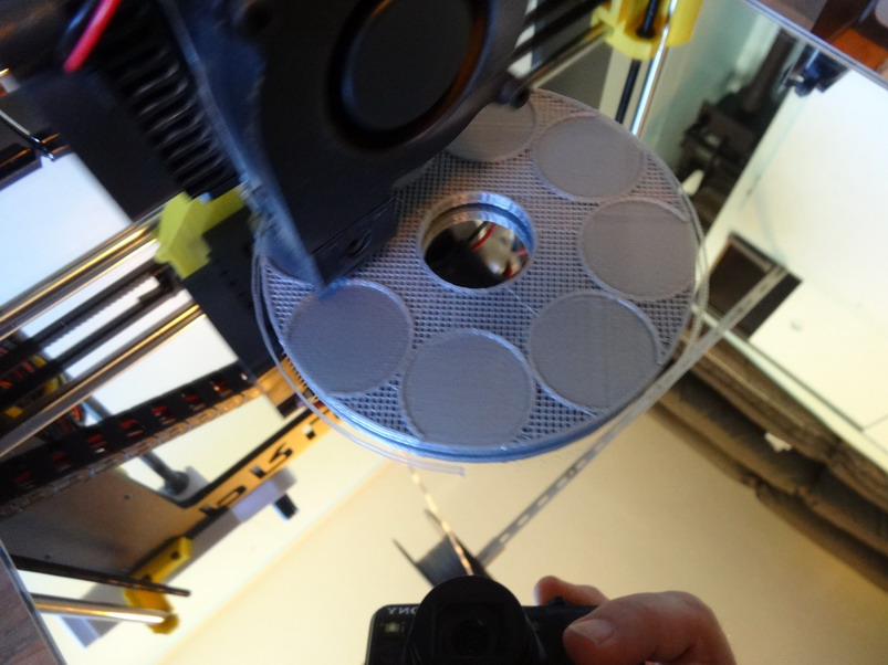
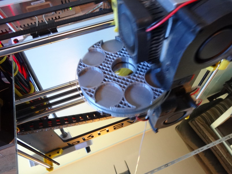
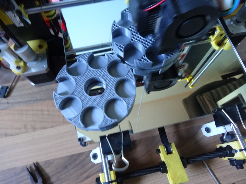
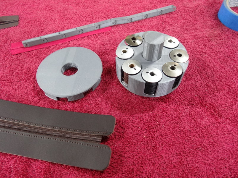
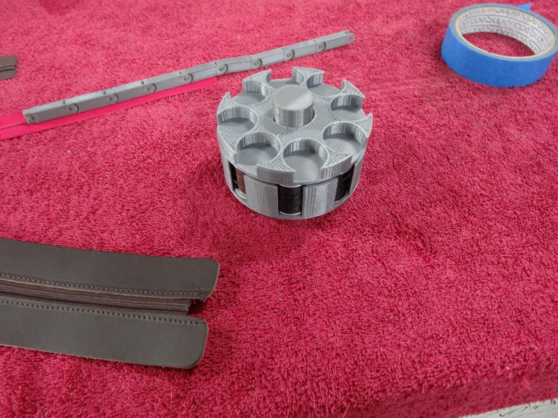
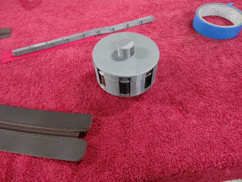
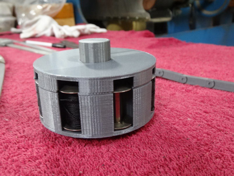
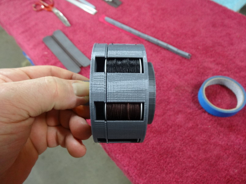
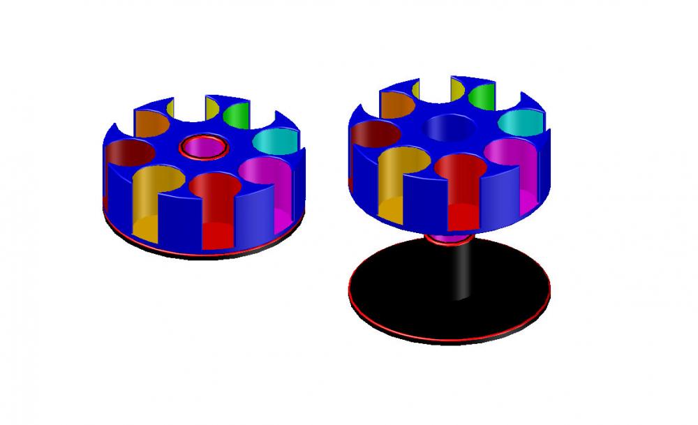
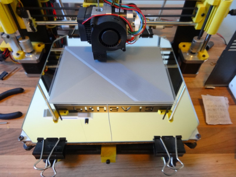
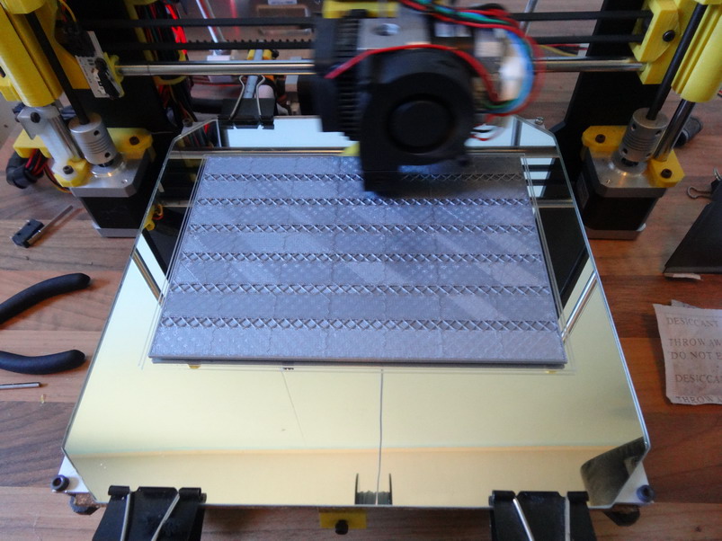
Thanks for that ......I think?? . Here is the results of the print out below. Note I mentioned there was a triangle thing hanging out which I was worried about, well I ignored it and it worked out alright. Those that are good at cleaning up this stuff please feel free to do so. I don't generally get these when I draw up and can'r remember the steps to get rid of it. It was faster for me to scape it off with a sharp knife. Clean up time on both pieces was about 1 minute if that. This first picture is as the stl files will give you without alterations and with bobbins installed ready to shoot. It works and spins well and the bobbins are easy enough to get out. I had a failure on my first print which for some reason the stepper motor on rare occasions jumps or misses a step and every thing thereafter keeps printing above on the wrong line. This next pic was that print and it failed about 10mm up Z. As the fill was set at 30% I changed the next 1 to 20% and slowed the print speed a little. Here I dropped the first print beside the new one once it was passed the same fail point and relaxed again. This pic shows how bad that triangle spike printed out. Not so bad. When things stuff up I sometimes think there's a reason and I think the failed print made me think of a top cover and I kind of like it and as well it shows if you print the axle piece longer you could place another on top if you wanted. This makes it easier to handle as well. If you are using the Curra program you can unlock the padlock in the scale section and just increase the Z height to make it as high as you want it. I had one off a different project and used it instead and that is why the top hole is not showing in this example. Showing the double up idea. Keep in mind that if you do the same scale trick in Curra to the Z height you could shorten the revolver part to make a better lid as well. As I said this can make the handling and revolving quite nice. Lastly now here are the stl files. Jeffs Bobbin Revolver1.stl Jeffs Bobbin Revolver2.stl Please post your results and versions here as well. Woops nearly forgot here a link to another progect you may find useful. Brian
-
Zipper installation multipurpose guide
RockyAussie replied to RockyAussie's topic in 3D Printers and Lasers
Note: I will try and get a No5 chain nylon and metal guides done over the next couple of weeks. I got a lot of bags to catch up on first. Brian -
Zipper installation multipurpose guide
RockyAussie replied to RockyAussie's topic in 3D Printers and Lasers
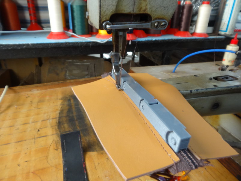
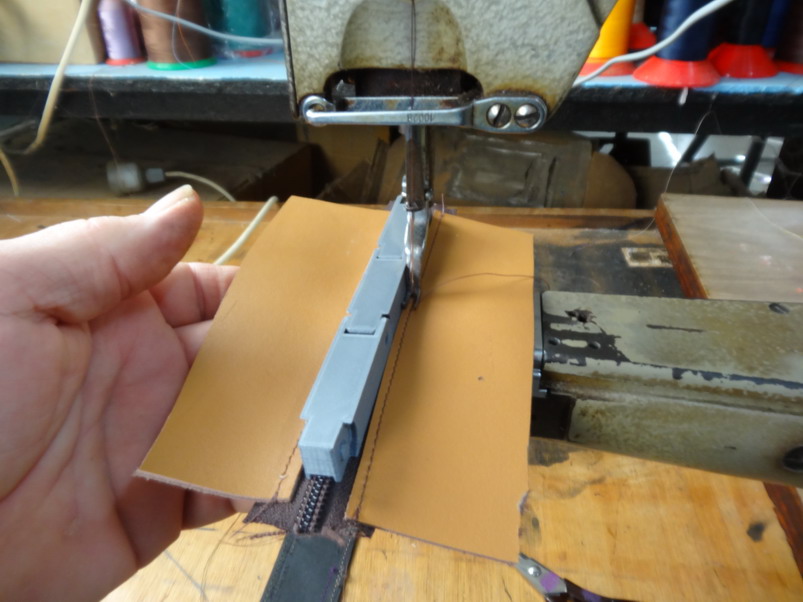
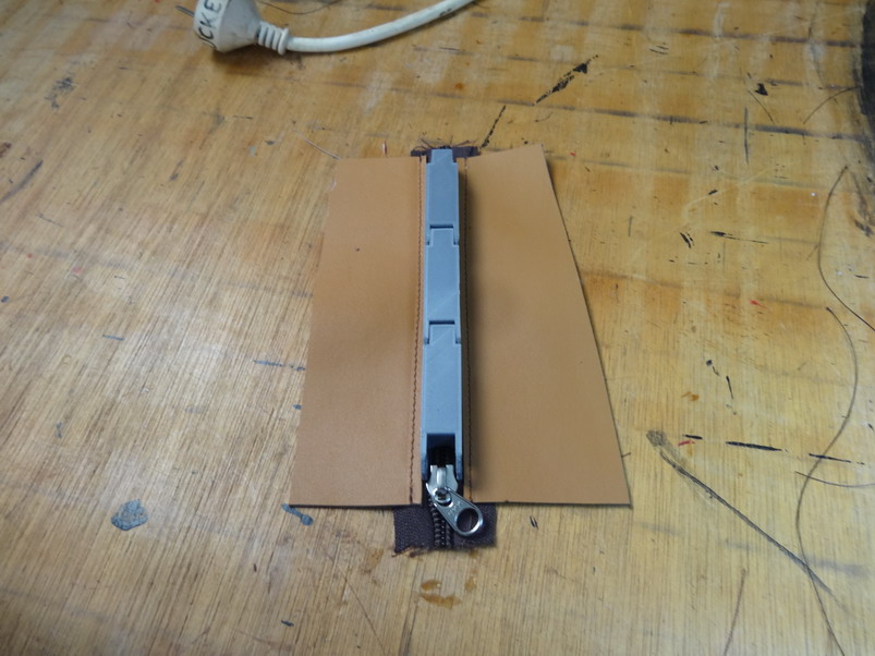
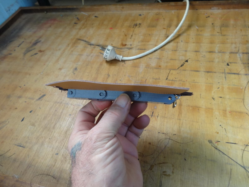
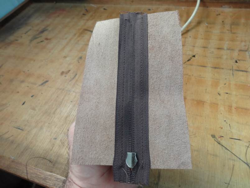
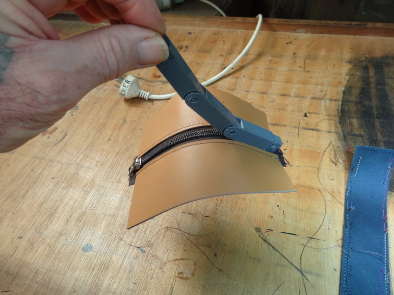
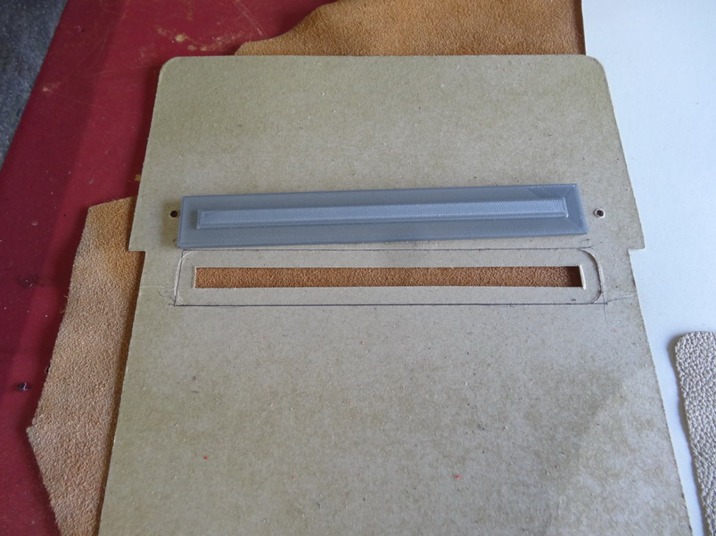
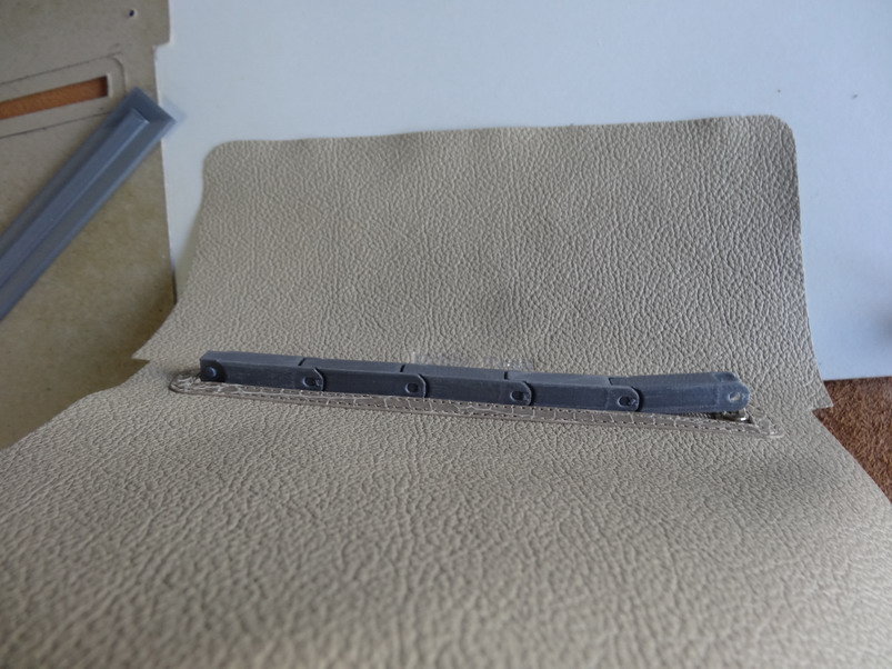
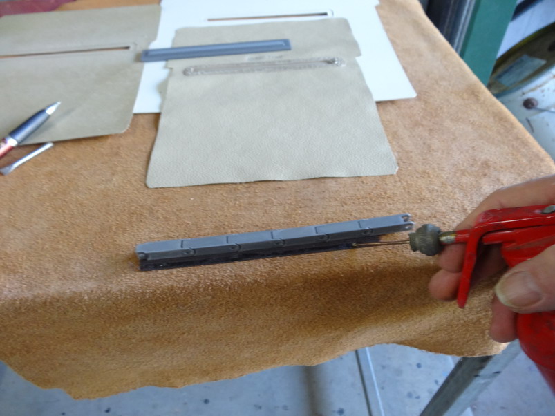
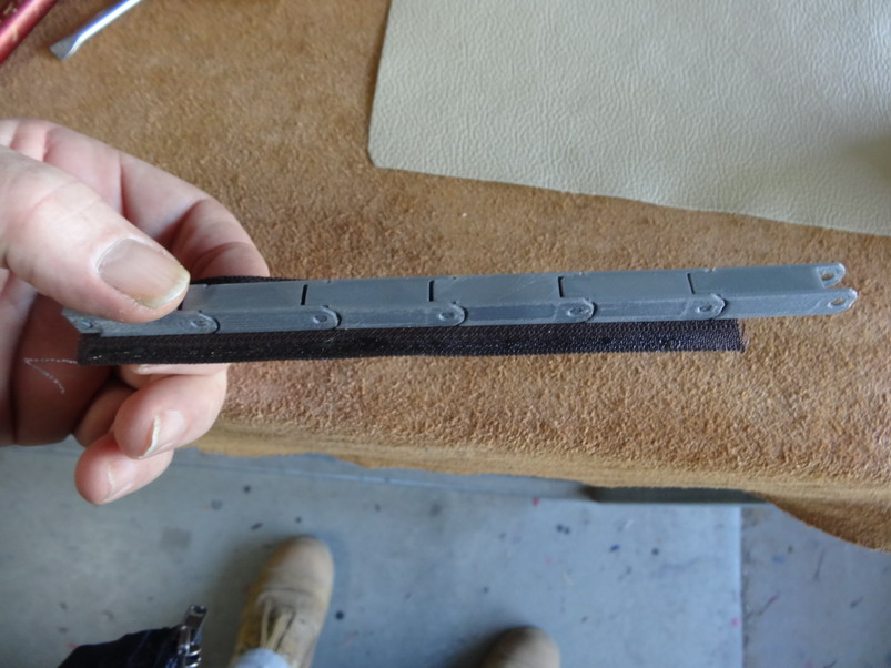
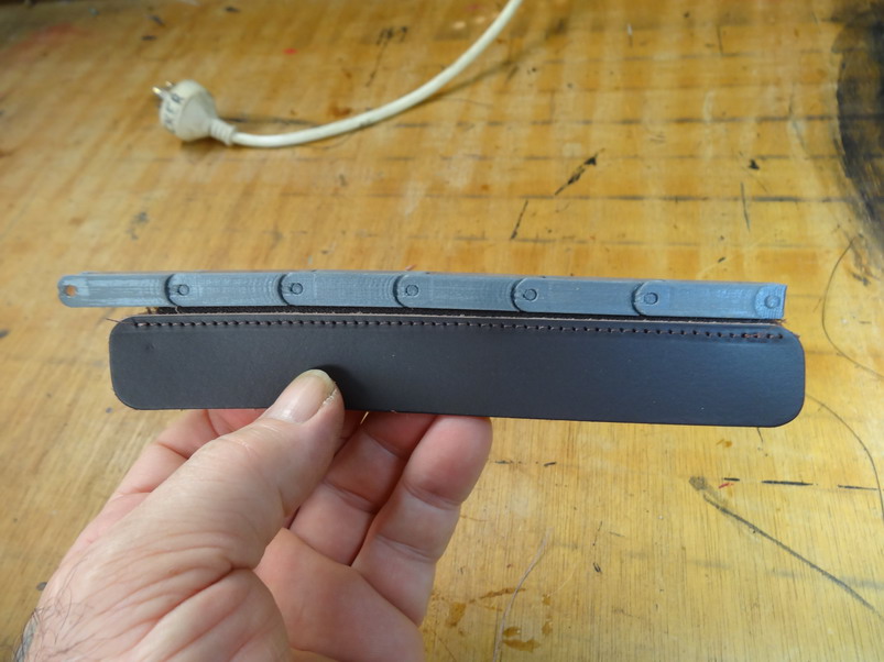
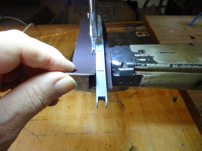
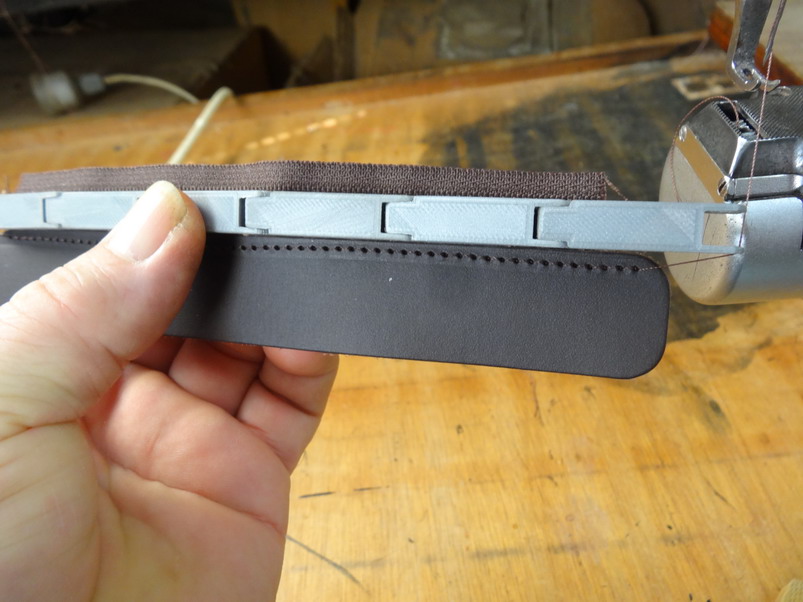
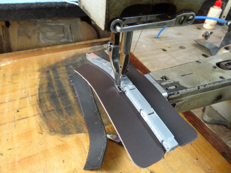
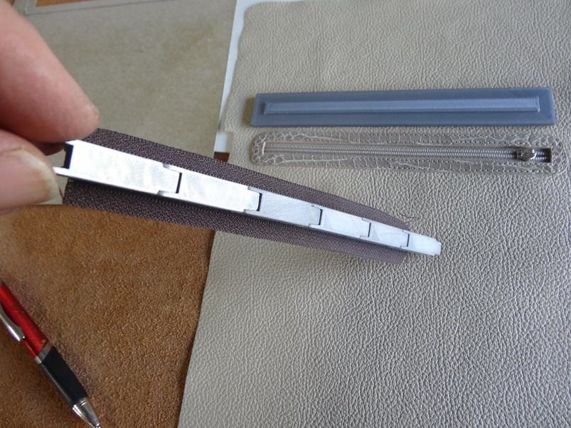
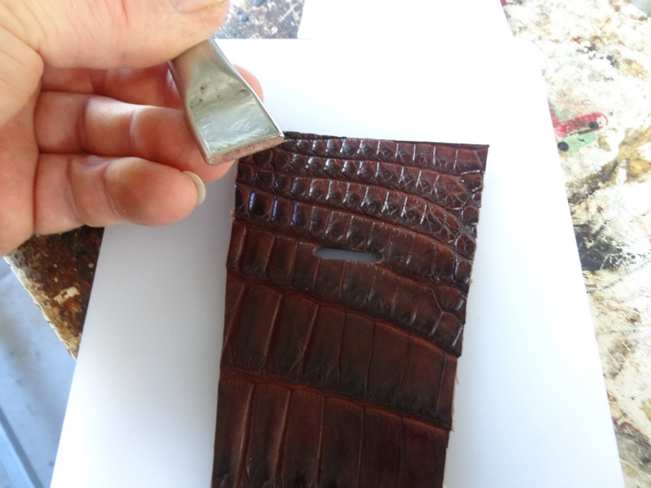
With the purpose made guide It is inserted into the hole and marked around the edges onto the back as shown. The width is the same as the outer edges of the zip. This is shown on one of the line up cardboards that is used for lining up the clicker knife when cutting the inside slot hole but this is what is done on the leather backing prior to gluing in the zipper into place. With the new guide the leather can be lowered over the hole to attach or leather can be butted up to the guide on each side. I found that you can hold the unit in one hand and apply with the other but this was hard to photograph by myself so ...... If you are not needing to glue into place it can be done by most sewing machines by holding the guide up against the foot and feeding in the leather against the guide as it goes through. I did a wobble first try but once I learned how to hold it it went quite easily. Other side is easier still As shown below the guide hangs on quite well but can pull out when you want to easily as well. That's it for now except here is the stl file ZIP JIG3 chain ny.stl Please if you make it and use it.... post some pics on here for other to see. Brian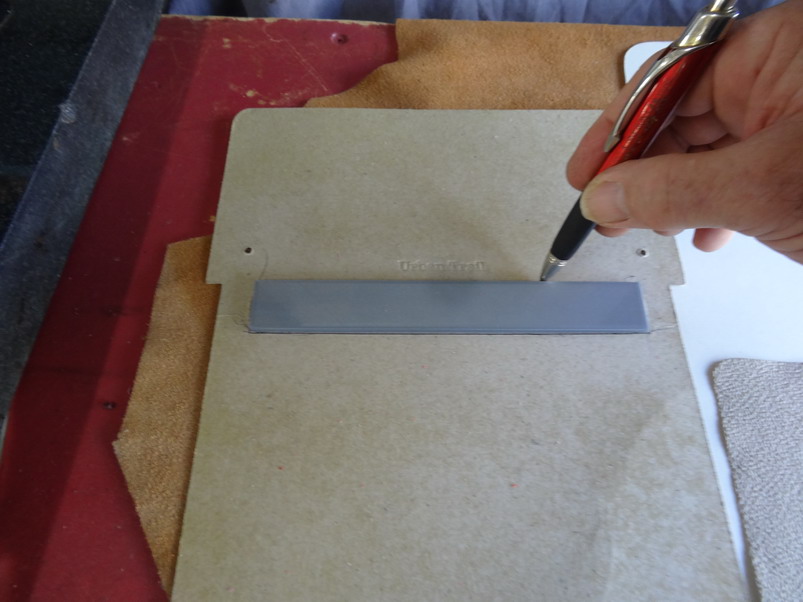
-
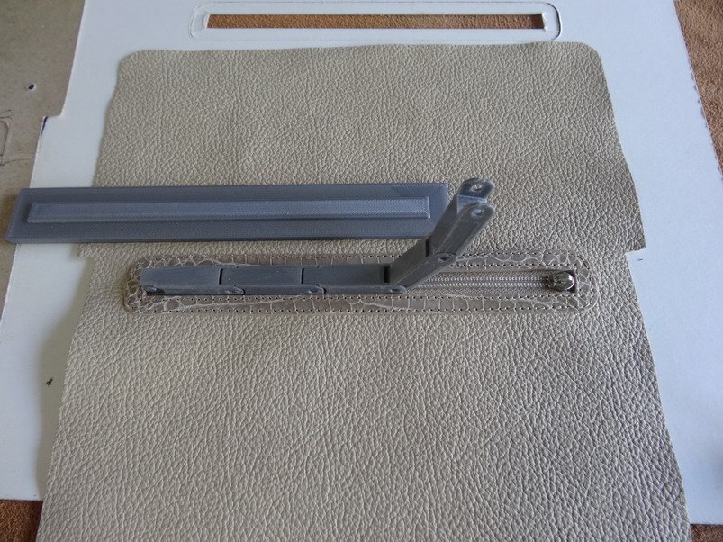
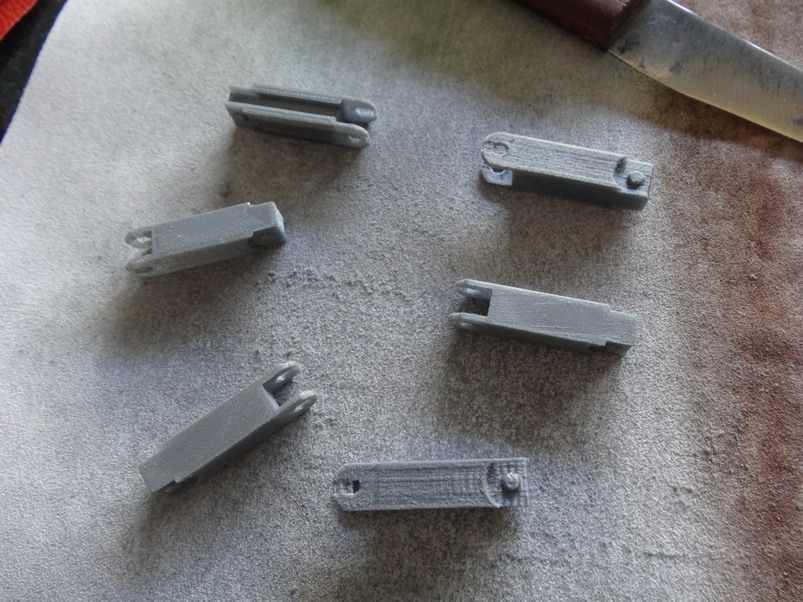
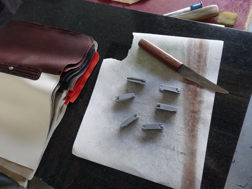
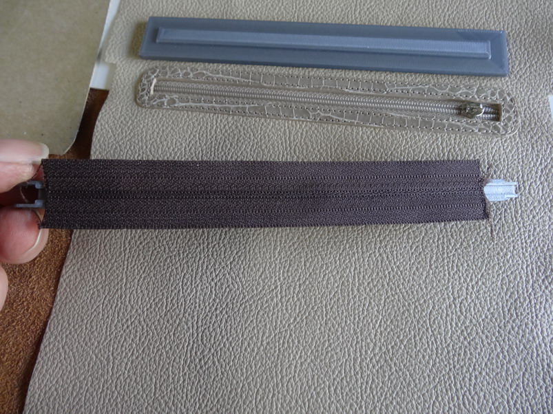
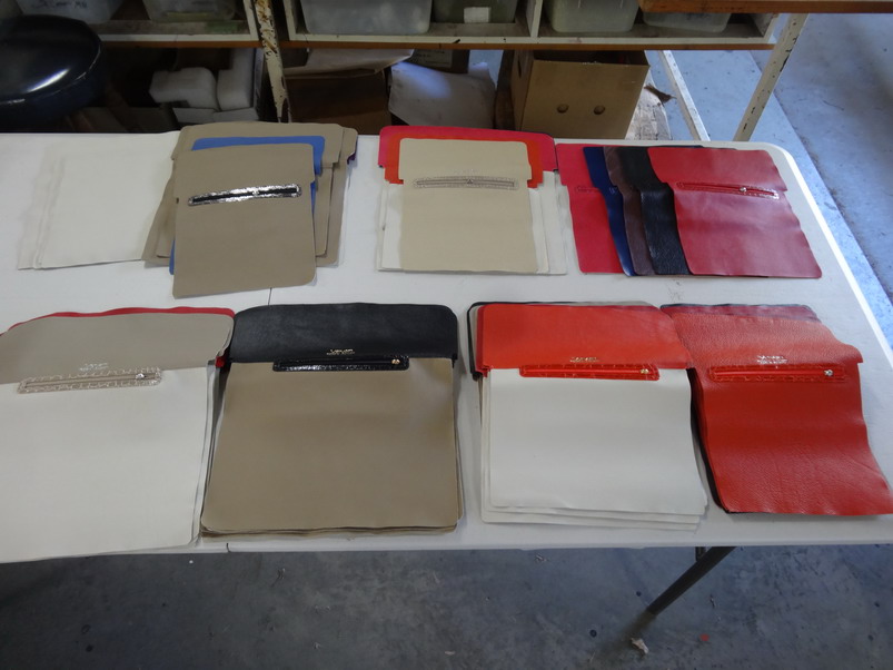
Awhile back I was asked about what guides were available for installing zippers into handbags and the like. Over the years I have made a huge range of jigs and guides for various different products but I knew of no multi-purpose type tool that could do this job with out making up special tools like my line up table I've detailed somewhat previously on this forum. What I have come up with no doubt will be improved in time but for my first effort I can say that this guide has performed better than I expected and for those that would like to make copies for themselves I will attach the stl file needed here which you are welcome to use for your own private use. If you just want to buy the parts let me know but I would like to offer it to @Uwe for his rights to sell within the US (if he wants it). This is due to the fact that I admire his contribution and help to so many on this forum and is just my own way of thanking him from us all. Also he has now the equipment for making this stuff and his integrity to service and quality I would trust. For those that want to print it out I will attach some pictures as well. In this first pic it shows the orientation I recommend to print as it give good strength to the 1mm legs and it works pretty well. I decided on a 30% fill using pla. In this case the 3 pieces took about 17 minutes I think. Bit rough and would be better on my old thing a bit slower perhaps. This is what it looks like finished on the platform. Bit rough above the holes but they work strongly anyway. Each piece I cleaned up with a knife and some sandpaper on a flat surface. This takes about 2 minutes to do well each. Now showing after cleaned up and ready to try out. A few more printed and cleaned up and pressed down onto No3 YKK nylon chain zip. Once the guide is pressed on the lot can be handled well as a single unit to work on. In the picture above you can see another printed guide made specifically for that length zip to make the position on the back for gluing the zipper into place. These bags linings below were all done using that method I will show more of further down. This shows what is wrong with doing good quality work......toooooo many bags to make. Over 50 croc bags in this lot and probably near as many to follow next month. Sorry I went off subject there a bit. I will load this now and have a coffee and be back shortly.
-
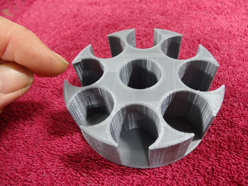
Hey Jeff ...you know that's off topic now in this forum? You gonna get us kicked back into the sewing machine section again as there is no wood work section that I've seen yet.. I been thinking about your drawing and the only thing that bothers me is the lack of seeing the colour clearly of me bobbins and with my bad shi memory I would not know where the hell I put that colour unless I painted beside the top or something like that. You being into holsters and guns and stuff I came up with this idea I have called Jeff's Bobbin Revolver The pic on the left shows both pieces assembled and able to revolve and the pic on the right ...blah blah. This pdf file below should open in a 3d way if you click on the picture when it opens. Unfortunately there is some little triangle thing you can see that I have to work out to remove maybe. I will give it a trial print tomorrow and let you know how it goes. I would have done it today but the printers been busy doing the new click together zip line up guide and more dam ring boxes. I'll post the zip stuff tomorrow as well in the sewing machine section first. They'll move it for me probably Jeffs Bobbin Revolver1.pdf Brian
-
Filament quality and even different colours can give a lot of variable results so I tend to do mostly work with this silver colour and run it on the hot side. Keeping the room warm can help a lot with that also. I'd like a large Perspex box over the top but that's just another on the gotta do list.
-
I thought about a lid but to be honest the cylinder machine that it will live with gets use every day and changing bobbins happens a lot so I thought it would just be a waste of time. with its flat base I don't think knocking it over is going to happen but I guess it could be stuck in place with double sided tape or something. Pla and a heated bed run at 65 degrees C. The plate is cleaned well with Isopropyl alcohol before every new print. Constabulary's idea looks good but I don't think the magnets should be needed at least if the 2 ends were blocked off. Might be a bit easier to knock over and lose them though. Yes ...that was my thinking as well and I suppose it should be there as well perhaps as a link or something.
-
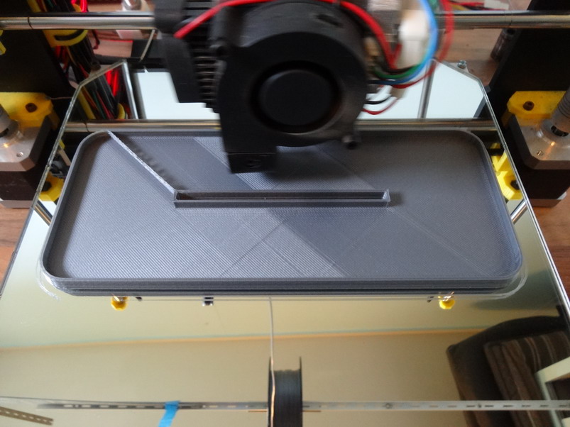
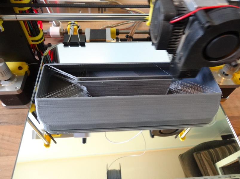
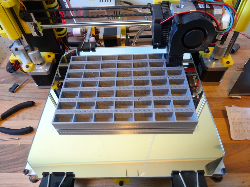
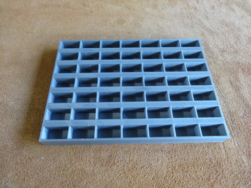
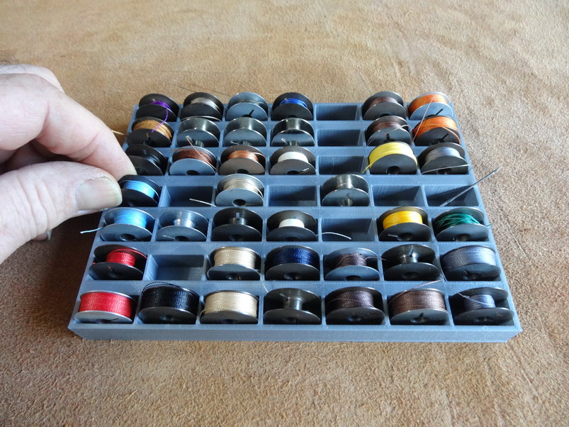
Not sure if this would be best in the 3D printer section or here but I thought I would share this bobbin rack case that I made up today. I have attached a stl file so it can be printed out if you like. I used a 20% fill with .8mm shell thickness settings on the printer. It uses 108 grams of filament at that and in Oz that's about $4.00 worth. It holds 49 bobbins and the L is 172mm x 125 W. The hole size for a bobbin is 12x23mm. BOBBIN CARRIER.stl 2mm thick base The hatch area is the gap area needed between bobbins to get your fingers onto each side of the bobbin to remove and replace easily. Works good .....I think I'll make one for the big Cowboy ones next. Am working on a snap together zip installation guide at the moment which all going well I will finish this week end. Cheers Brian
-
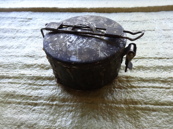
If your really stuck you could just make one.I have in the past made many with various pipe pieces like this one in the picture. I try and remove any seam bur inside the pipe a bit first then find a bit of metal the width I want the hole to end up in width. I squeeze the end in a big vice and hammer a bit until I get what I want. AS you get close to the oval put in the metal piece to help keep the width right and in shape. Sounds harder than it looks. Normally I find a bolt to fit in the top hole and hammer down on it.

-
Cobra 4 presser foot leaving marks
RockyAussie replied to aaron8771's topic in Leather Sewing Machines
Stick the cardboard to the feet? just kidding......answer I think is just get wider feet under there.
